Multi-cavity circulating ventilation type control cabinet and production process thereof
What is Al technical title?
Al technical title is built by PatSnap Al team. It summarizes the technical point description of the patent document.
A technology of circulating ventilation and production process, applied in the field of control cabinets, can solve the problems of occupying space, cluttered equipment placement, poor heat dissipation effect, etc., and achieve the effect of reducing dust deposition and improving heat dissipation effect.
Active Publication Date: 2021-01-26
江苏东皋电气有限公司
View PDF21 Cites 1 Cited by
Summary
Abstract
Description
Claims
Application Information
AI Technical Summary
This helps you quickly interpret patents by identifying the three key elements:
Problems solved by technology
Method used
Benefits of technology
Problems solved by technology
[0002] The control cabinet is to assemble switchgear, measuring instruments, protective appliances and auxiliary equipment in a closed or semi-closed metal cabinet or on a screen width according to the requirements of electrical wiring. It is an insulating cabinet for installing electrical equipment, so it is necessary to ensure good Ventilation and heat dissipation, but the ventilation and heat dissipation function of the existing control cabinet is relatively simple, only part of the control cabinet can be cooled, and the heat dissipation effect is poor. The existing control cabinet has only one cavity for placing equipment, which will lead to messy equipment placement. It is inconvenient to overhaul, the existing control cabinet uses a door with an opening and closing structure, which takes up a lot of space when it is opened, and is inconvenient to place in a narrow place
Method used
Image
Click on the blue label to locate the original text in one second.
Reading with bidirectional positioning of images and text.
Examples
Embodiment Construction
[0043] The following will clearly and completely describe the technical solutions in the embodiments of the present invention with reference to the accompanying drawings in the embodiments of the present invention. Obviously, the described embodiments are only some, not all, embodiments of the present invention. Based on the embodiments of the present invention, all other embodiments obtained by persons of ordinary skill in the art without making creative efforts belong to the protection scope of the present invention.
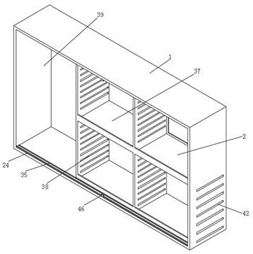
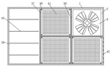
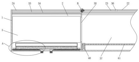
[0044] see Figure 1-5, the present invention provides a technical solution: a multi-cavity circulating ventilation control cabinet and its production process, including a cabinet 1, an air chamber 2, a fan 3, a first slot 4, a baffle 5, a bracket 6, a dustproof Cotton 7, holding box 8, desiccant 9, first pin 10, first block 11, slot 12, first connecting block 13, second through groove 14, guide rod 15, first spring 16, second connecting Block 17, first guide...
PUM
Abstract
The invention discloses a multi-cavity circulating ventilation type control cabinet and a production process thereof. The cabinet comprises a cabinet body, an air chamber, a draught fan, a first through groove, a baffle, a support, dustproof cotton, a containing box, a drying agent, a first plug pin, a first clamping block, a first sliding door, a first sliding groove, a first sliding rail, a second sliding door, a third sliding groove, a second sliding rail, a notch, a second cavity, a first sealing strip, a check block and a second sealing strip. The production process comprises the steps of: 1, manufacturing main components; 2, installing draught fan; 3, installing the sliding door; and 4, performing equipment inspection. Compared with an existing control cabinet, the control cabinet has the advantages that a circulating ventilation function is designed, circulating flow of air in the cabinet body can be achieved, the heat dissipation effect is improved, deposition of dust in the cabinet body is reduced, multiple cavities are designed, classified placement of equipment can be achieved, a sliding door device is designed, no extra space is occupied in the using process, and the multi-cavity circulating ventilation type control cabinet is suitable for various areas with narrow spaces.
Description
technical field [0001] The invention relates to the technical field of control cabinets, in particular to a multi-cavity circulating ventilation control cabinet and a production process thereof. Background technique [0002] The control cabinet is to assemble switchgear, measuring instruments, protective appliances and auxiliary equipment in a closed or semi-closed metal cabinet or on a screen width according to the requirements of electrical wiring. It is an insulating cabinet for installing electrical equipment, so it is necessary to ensure good Ventilation and heat dissipation, but the ventilation and heat dissipation function of the existing control cabinet is relatively simple, only part of the control cabinet can be cooled, and the heat dissipation effect is poor. The existing control cabinet has only one cavity for placing equipment, which will lead to messy equipment placement. It is inconvenient to overhaul. The existing control cabinet uses a door with an opening a...
Claims
Application Information
Patent Timeline
Application Date:The date an application was filed.
Publication Date:The date a patent or application was officially published.
First Publication Date:The earliest publication date of a patent with the same application number.
Issue Date:Publication date of the patent grant document.
PCT Entry Date:The Entry date of PCT National Phase.
Estimated Expiry Date:The statutory expiry date of a patent right according to the Patent Law, and it is the longest term of protection that the patent right can achieve without the termination of the patent right due to other reasons(Term extension factor has been taken into account ).
Invalid Date:Actual expiry date is based on effective date or publication date of legal transaction data of invalid patent.