
Coating device and coating method

A coating device and coating technology are applied in the field of coating device and coating method to achieve the effect of rapid operation and improved connection

Active Publication Date: 2019-04-05
HOMAG HOLZBEARBEITUNGSSYST
View PDF11 Cites 1 Cited by
  • Summary
  • Abstract
  • Description
  • Claims
  • Application Information

AI Technical Summary

Problems solved by technology

Other preferred embodiments are described below

Method used


Image

  • Coating device and coating method
  • Coating device and coating method

Examples


no. 1 approach 1

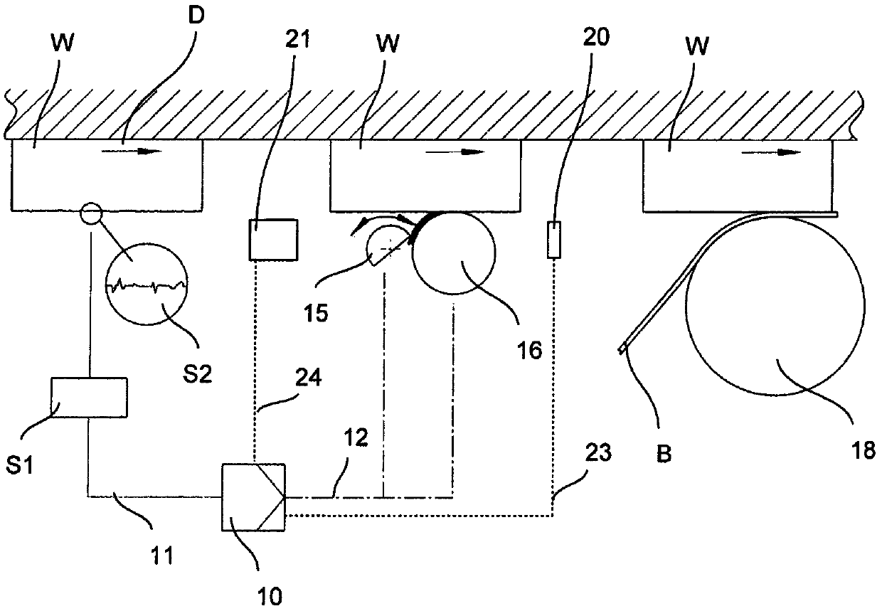
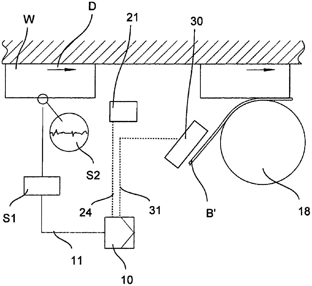
[0064] Like the first embodiment, the coating device according to the second embodiment comprises a first sensor S1 and a second sensor S2 connected to the control device 10 by a line 11 . Furthermore, a manipulation device 21 is provided which is connected to the control device 10 via a line 24 .

[0065] The second embodiment differs from the first embodiment in that instead of applying the adhesive on the workpiece, the activation of the adhesive provided on the coating material B' takes place. The coating material B' can be a coextruded coating material or a support material provided with an adhesive layer.

[0066] Thus, according to a second embodiment, an activation device 30 is provided, which is connected to the control device 10 by a line 30 . The activation device 30 is configured to activate the adhesive or adhesion-promoting layer of the coating material B', in particular to heat it.

[0067] If an elevated surface temperature on the workpiece is detected by the...


PUM


Abstract

The present invention relates to a coating device which, in particular, is used to coat a narrow side of a plate-shaped workpiece with a coating material. Furthermore, the present invention relates toa coating method which, in particular, is used to coat a narrow side of a plate-shaped workpiece with a coating material. The coating device comprises a detection device (S1, S2) for detecting a surface property on the surface of the workpiece (W) to be coated and a device for acting on the adhesive to be used based on the detection result of the detection device.

Description

technical field [0001] The invention relates to a coating device, in particular for coating narrow sides of plate-shaped workpieces with a coating material. Furthermore, the invention relates to a coating method, in particular for coating the narrow side of a plate-shaped workpiece with a coating material. Such a coating device and such a coating method are used in particular in the field of furniture and components industry. Background technique [0002] When coating the narrow sides of plate-shaped workpieces, it is known in the prior art to use pre-coated coating materials, the adhesive layer of which is activated shortly before the coating material is applied to the narrow sides of the workpiece. Coextruded coating materials are also known in this regard. [0003] According to another possibility, an adhesive can be provided to the coating material before it is applied to the narrow side of the workpiece. [0004] Furthermore, devices are known in which the adhesive i...

Claims


Application Information

Patent Timeline
IPC IPC(8): B27G11/00
CPCB27G11/00B27D5/003B32B37/12B32B41/00B32B7/12
Inventor 约翰内斯·施密德
Owner HOMAG HOLZBEARBEITUNGSSYST
Learn More