Hot tub with magnetically coupled headrest

Inactive Publication Date: 2019-10-31
LPI
View PDF4 Cites 0 Cited by
  • Summary
  • Abstract
  • Description
  • Claims
  • Application Information

AI Technical Summary

Benefits of technology

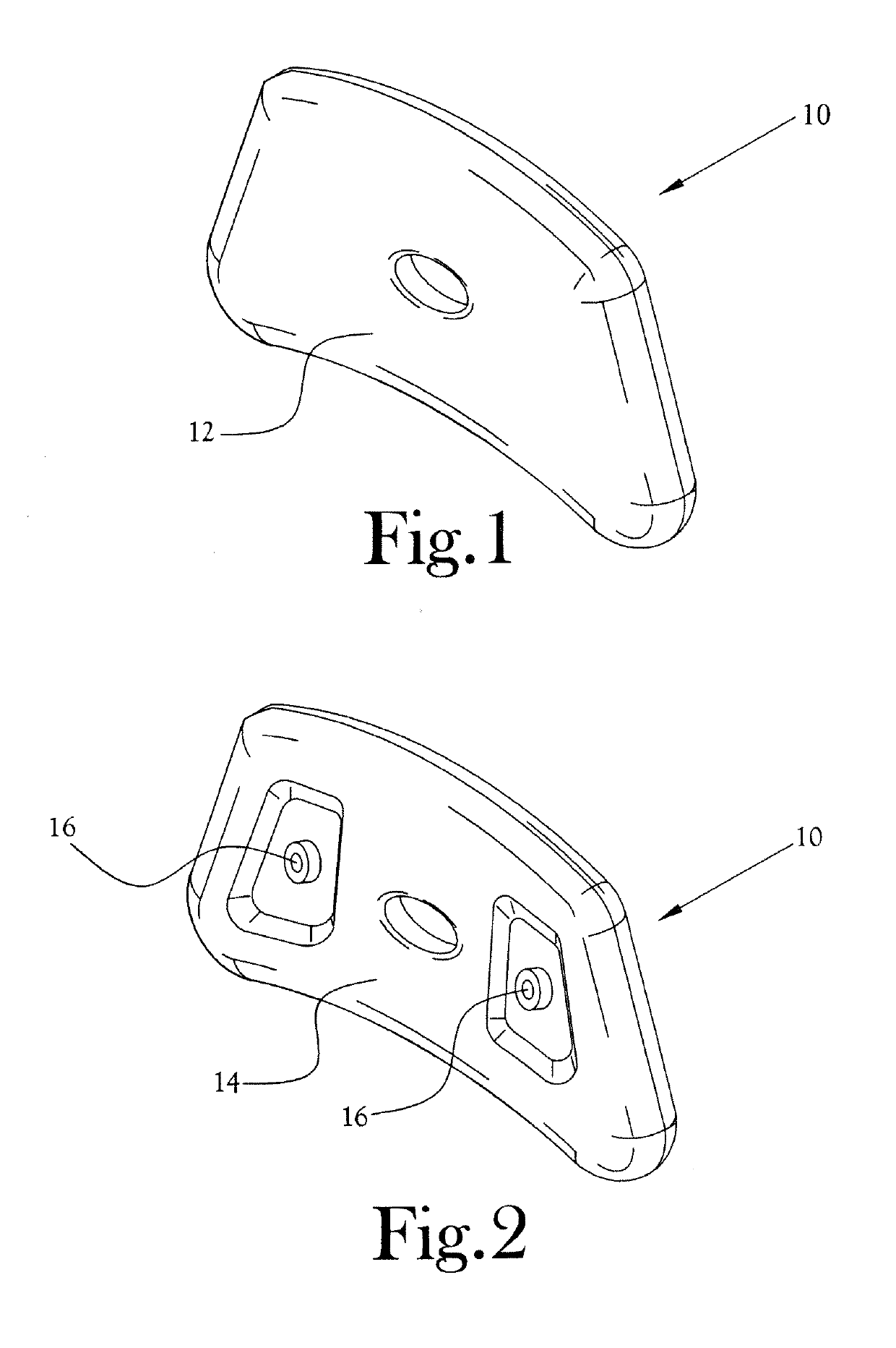
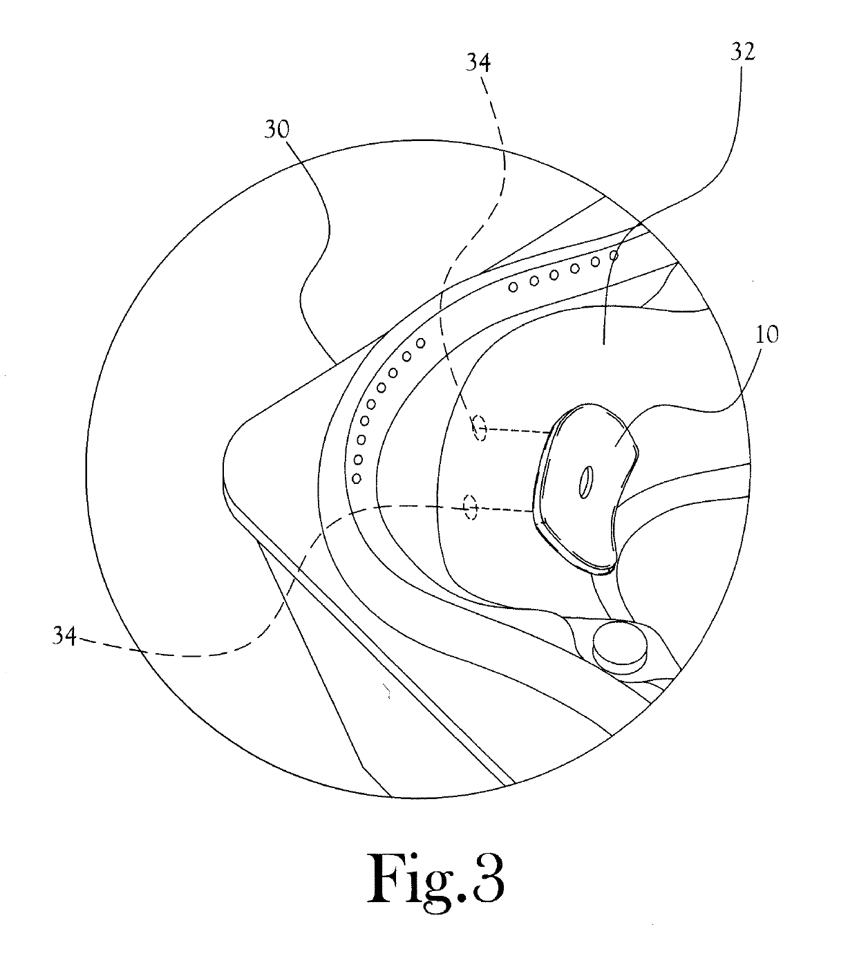
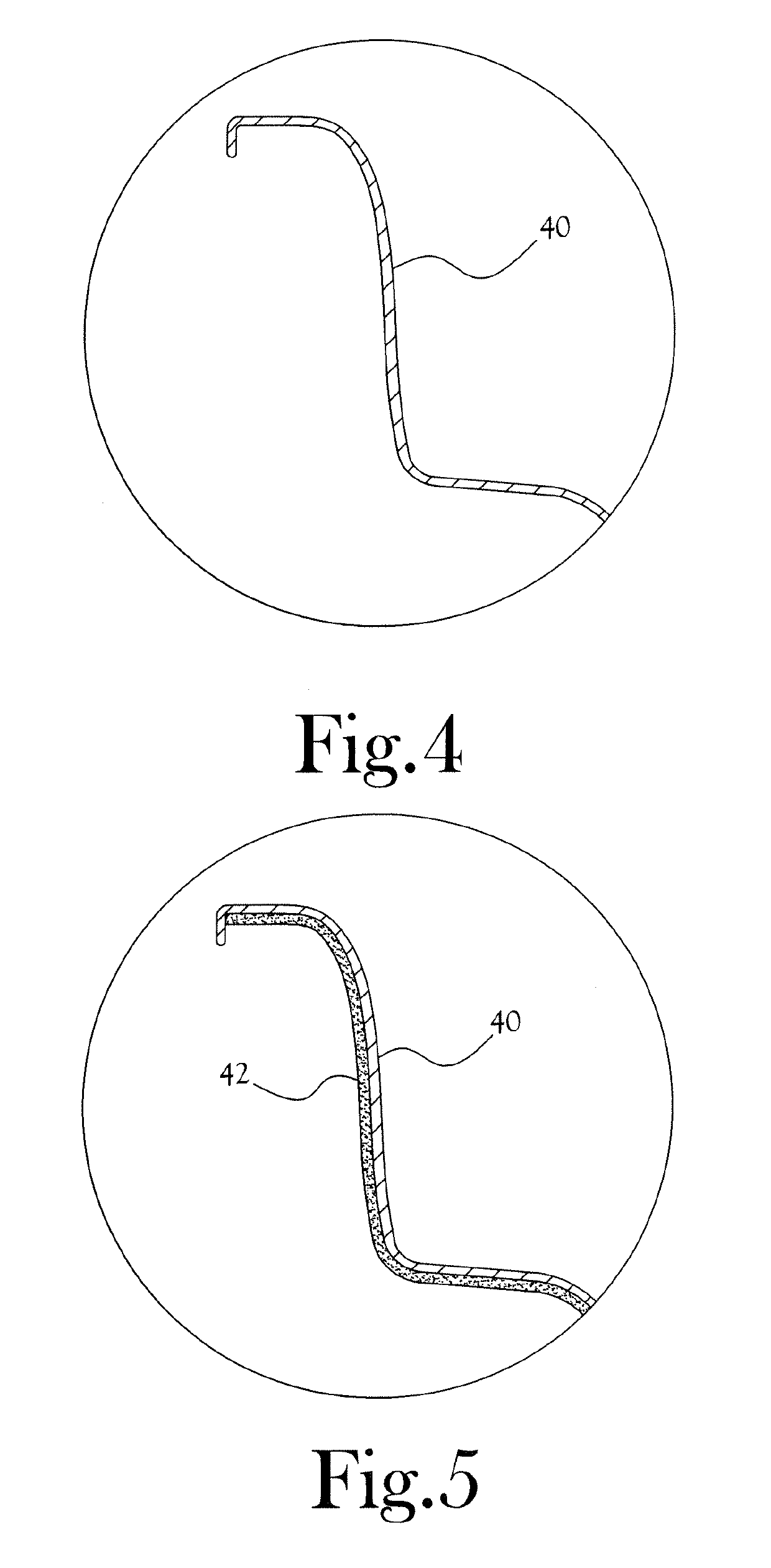
[0006]According to various example embodiments of the present general inventive concept, a hot tub, and a method of constructing s

Problems solved by technology

However, as such accommodations are typically provided manually by handheld drills, the forming and placement of such holes are prone to quality control problems such as misalignment, overall misplacement, damage to the hot tub shell, and so on.
Also, headrests installed by such conventional methods and material are difficult to remove fro

Method used


Image

  • Hot tub with magnetically coupled headrest
  • Hot tub with magnetically coupled headrest
  • Hot tub with magnetically coupled headrest

Examples


Embodiment Construction

[0016]Reference will now be made to the example embodiments of the present general inventive concept, examples of which are illustrated in the accompanying drawings and illustrations. The example embodiments are described herein in order to explain the present general inventive concept by referring to the figures.

[0017]The following detailed description is provided to assist the reader in gaining a comprehensive understanding of the structures and fabrication techniques described herein. Accordingly, various changes, modification, and equivalents of the structures and fabrication techniques described herein will be suggested to those of ordinary skill in the art. The progression of fabrication operations described are merely examples, however, and the sequence type of operations is not limited to that set forth herein and may be changed as is known in the art, with the exception of operations necessarily occurring in a certain order. Also, description of well-known functions and con...


PUM


Abstract

A hot tub, and a method of construction of a hot tub, the hot tub including a hot tub basin provided with one or more first magnetic members affixed at an underside of an exposed surface of the hot tub basin corresponding to a headrest region, and a headrest provided with one or more second magnetic members configured to be attracted to the first magnetic members such that the headrest is selectively attachable to the headrest region by the attraction between the first and second magnetic members.

Description

CROSS-REFERENCE TO RELATED APPLICATIONS[0001]This application claims the benefit of U.S. Provisional Patent Application Ser. No. 62 / 580,190, filed on Nov. 1, 2017, which is incorporated herein in its entirety by reference.FIELD OF INVENTION[0002]The present general inventive concept relates to the construction of a hot tub, and, more particularly, to a hot tub having a magnetically coupled headrest.BACKGROUND[0003]Hot tubs and similar devices are used for recreation, exercise, and physical therapy. Hot tubs are often employed for treating sore muscles or for relaxation after exercise or rigorous physical activity. The basin of a hot tub is typically molded so as to have several defined seats, and headrests, often cushioned, are often provided to correspond to those defined seats such that a user sitting in the seat may comfortably rest his or her head on the headrest.[0004]As the headrests are typically provided with a padding component, these pieces will not be formed in the same p...

Claims


Application Information

Patent Timeline
IPC IPC(8): A47K3/12
CPCA47K3/125A47K3/001A61H33/6005A61H2201/0119A61H2201/0192A61H2201/1604
Inventor HELGERT, THEODORE
Owner LPI
Why Eureka
Try Eureka