

Bottle cap with automatic suction function
A bottle cap, automatic technology, applied in the direction of capping with auxiliary device, sealing member with auxiliary device, closing, etc., can solve the problems of pollution, flowing to the outer bottle wall, affecting the liquid, etc., to achieve the effect of convenient use
- Summary
- Abstract
- Description
- Claims
- Application Information
AI Technical Summary
Problems solved by technology
Method used
Image

Examples
Embodiment Construction
[0029] Below with reference to accompanying drawing and in conjunction with embodiment, describe the present invention in detail:
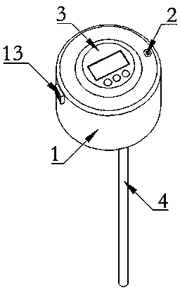
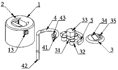
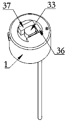
[0030] Such as Figure 1-3 As shown, a kind of automatic suction bottle cap is mainly made up of bottle cap shell 1, motor 33, roller 32, controller 36, power supply 37, flexible straw 4 and stopper 5, has a groove on the upper surface of bottle cap shell 1 , motor 33, roller 32, controller 36, power supply 37 are all placed in this groove, controller 36 controls motor 33 work, power supply 37 is connected together with controller 36, utilizes power supply 37 to be the electronics in this bottle cap. The device provides electric energy, the motor 33 is fixed together with the driving wheel 31 through a rod, the roller 32 is in contact with the driving wheel 31, and the driving wheel 31 is driven to rotate by the rotation of the motor, and the driving wheel 31 rolls with the roller 32.
[0031] A control board cover 3 is fixed on the groove of the...
PUM
 Abstract
Description
Claims
Application Information