
On-line automatic crane operating state monitoring system based on internet

A technology of operating status and monitoring system, applied in the directions of transportation and packaging, load hanging components, etc., can solve the problems of not being able to carry out comprehensive monitoring, the camera cannot be rotated, and there is no protective device, so as to expand the monitoring range and increase the monitoring Area, simple operation effect

Active Publication Date: 2019-04-05
广东南桂起重机械有限公司
View PDF9 Cites 2 Cited by
  • Summary
  • Abstract
  • Description
  • Claims
  • Application Information

AI Technical Summary

Problems solved by technology

[0003] In the current tower crane work, it is often necessary to monitor the tower crane and transmit it to the video player through the Internet, which can save the trouble of wiring. In this utility model, the monitoring camera is fixed. Installed, and there is no protective device for the monitoring camera, so it is easy to cause damage to the camera, and the fixedly installed camera cannot be rotated, so there will be a large blind spot in the monitoring angle, and comprehensive monitoring cannot be carried out, so we propose An Internet-based online automatic crane operation status monitoring system for solving the above-mentioned problems

Method used


Image

  • On-line automatic crane operating state monitoring system based on internet
  • On-line automatic crane operating state monitoring system based on internet
  • On-line automatic crane operating state monitoring system based on internet

Examples


Embodiment

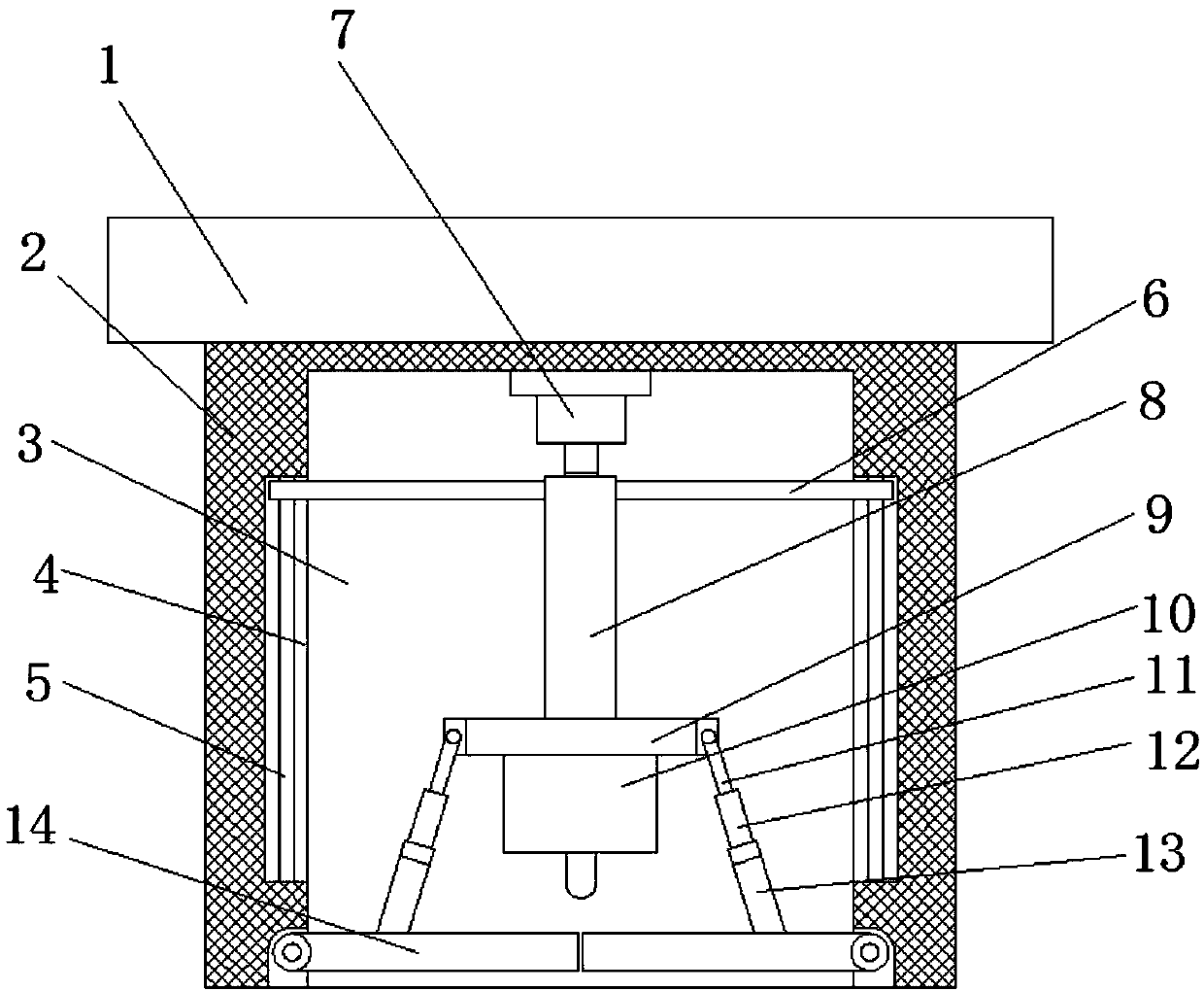
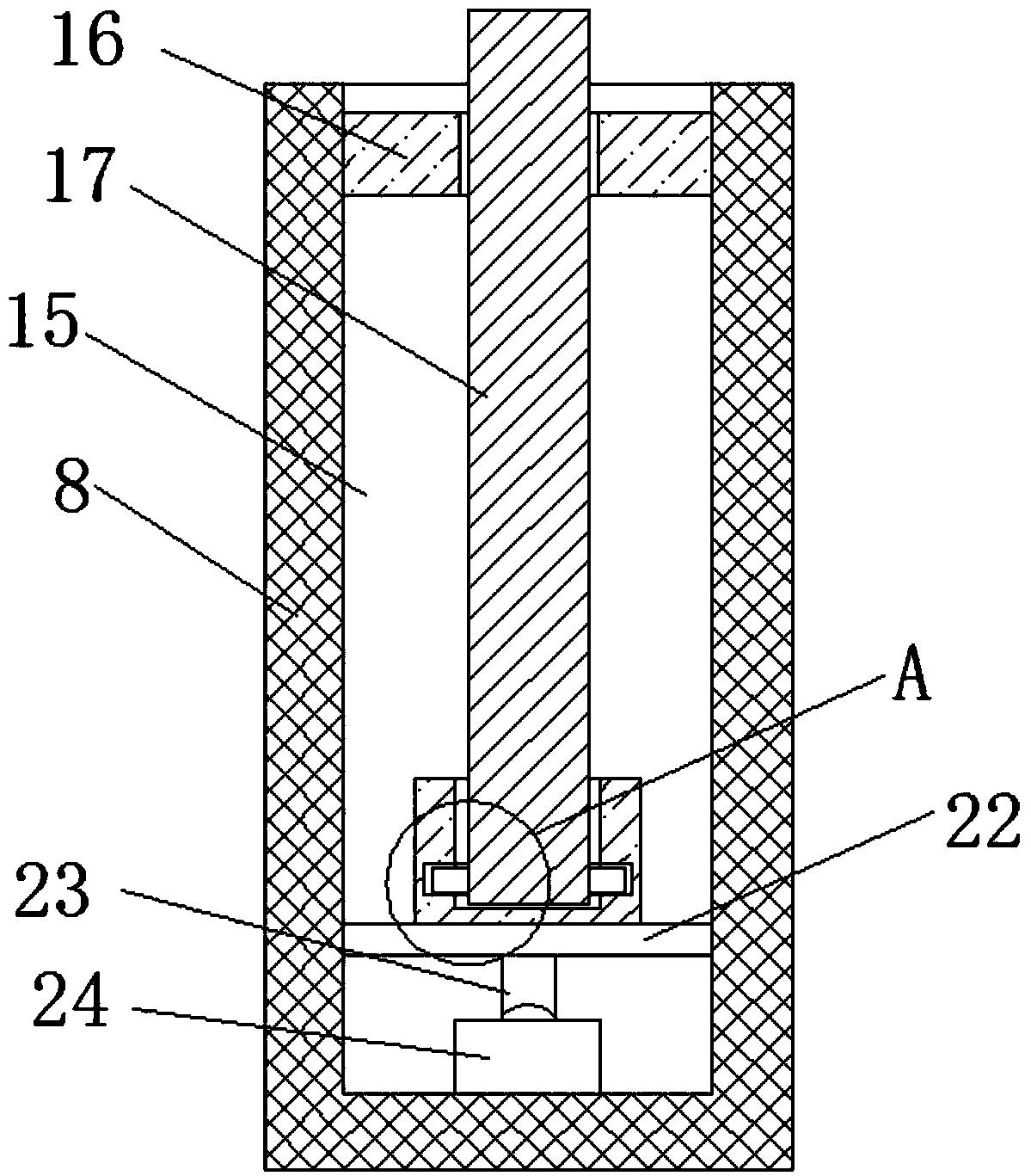
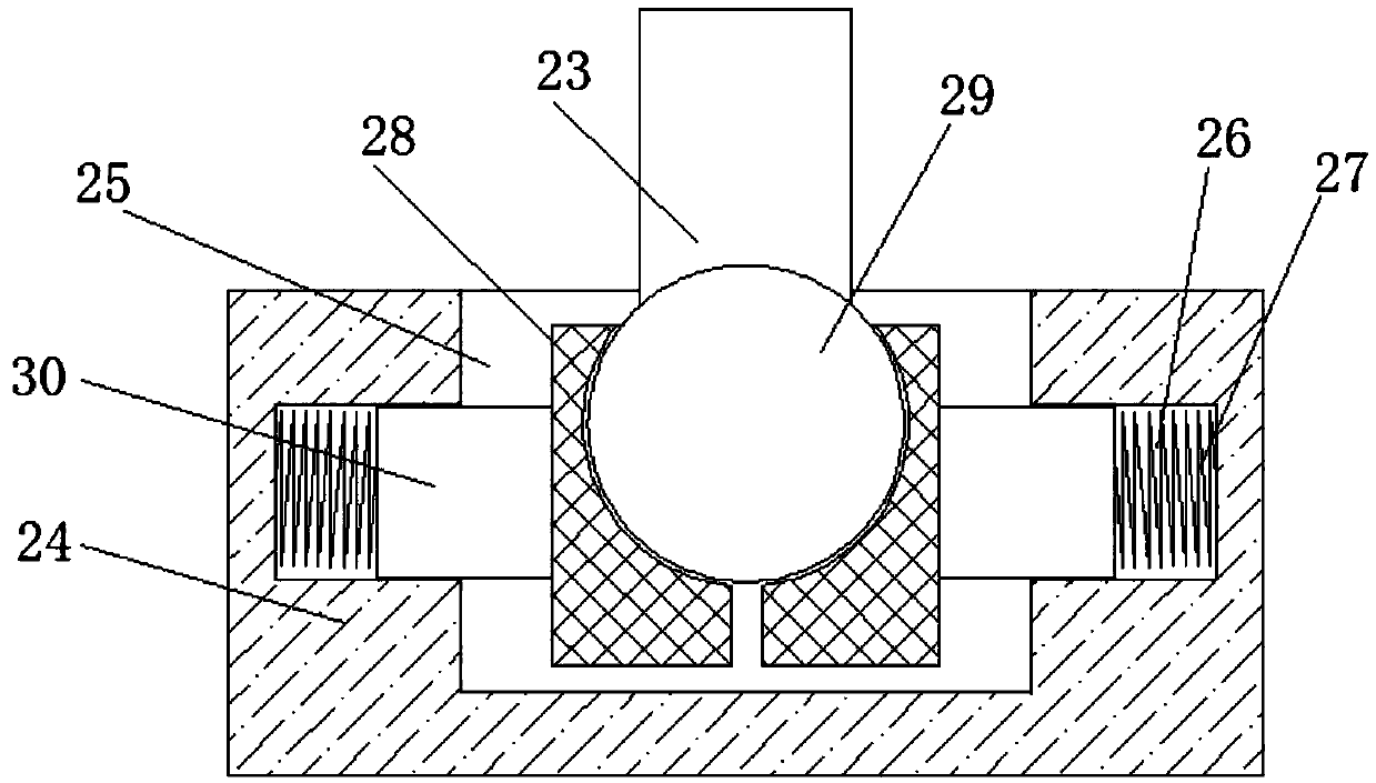
[0025] refer to Figure 1-5 In this embodiment, an online automatic crane operation status monitoring system based on the Internet is proposed. The inner walls of both sides of the 3 are provided with chute 4, and a slide bar 5 is fixedly installed in the chute 4, and the slide bar 5 is slidably connected with a limit rod 6, and the ends of the two limit rods 6 that are close to each other extend to the receiving end. The same lifting column 8 is fixedly installed in the groove 3, and the first driving motor 7 is fixedly installed on the top inner wall of the receiving groove 3, and the output shaft of the first driving motor 7 is fixedly installed with a threaded column 17, and the threaded column 17 and The lifting column 8 is threadedly connected, the bottom of the lifting column 8 is fixedly equipped with a connecting plate 9, the top of the connecting plate 9 is fixedly installed with a rotating seat 10, the bottom of the rotating seat 10 is rotatably connected with a cam...


PUM


Abstract

The invention discloses an on-line automatic crane operating state monitoring system based on internet. The on-line automatic crane operating state monitoring system based on the internet comprises amounting plate, a protective seat is fixedly mounted at the bottom of the mounting plate, a storage groove is formed in the bottom of the protective seat, sliding grooves are formed in the inner wallsof two sides of the storage groove, and sliding rods are fixedly mounted in the sliding grooves. Limiting rods are slidably connected to the sliding rods, the ends, close to one other, of the two limiting rods extend into the storage groove and a same lifting column is fixedly mounted at the ends, close to one other, of the two limiting rods, and a first driving motor is fixedly mounted on the inner wall of the top of the storage groove. The on-line automatic crane operating state monitoring system based on the internet is simple in operation, can shift a camera out of the storage groove by starting the first driving motor, then, a second driving motor is started, a rotating plate can be driven to rotate, so that the camera is driven to rotate, the monitoring area can be effectively increased, the camera can be protected when the camera is not used, and the camera is prevented from being damaged.

Description

technical field [0001] The invention relates to the technical field of cranes, in particular to an Internet-based online automatic crane operation state monitoring system. Background technique [0002] The tower crane is a jib crane with a tower body, self-installation and a long rotatable jib. The jib is installed on the upper part of the tall tower. It is especially suitable for lifting operations when building tall buildings, mainly using hooks to lift heavy objects. It consists of three parts: metal structure, working mechanism and electrical system. The notification number: CN204474200U discloses a dynamic multifunctional monitoring system for tower crane lifting equipment, which relates to the technical field of tower crane lifting equipment monitoring. The utility model has four wireless monitoring devices for monitoring tower cranes, and the wireless monitoring devices transmit the pictures collected by them to the smart devices; the first wireless monitoring devic...

Claims


Application Information

Patent Timeline
Patent Type & Authority Applications(China)
IPC IPC(8): B66C13/16
CPCB66C13/16
Inventor 江绍庭冯雨龙长生黄志东
Owner 广东南桂起重机械有限公司
Learn More