
Rear-bending type impeller

An impeller, curved technology, applied in non-variable-capacity pumps, components of pumping devices for elastic fluids, machines/engines, etc. The effect of improving design efficiency, good performance and improving controllability

Active Publication Date: 2019-04-05
FOSHAN CITY NANHAI POPULA FAN
View PDF0 Cites 0 Cited by
  • Summary
  • Abstract
  • Description
  • Claims
  • Application Information

AI Technical Summary

Problems solved by technology

[0003] The technical problem to be solved by the present invention is to solve the problem that the traditional centrifugal impeller has a single structure and cannot conveniently adjust the wind speed and air volume

Method used


Image

  • Rear-bending type impeller
  • Rear-bending type impeller
  • Rear-bending type impeller

Examples


Embodiment Construction

[0025] The idea, specific structure and technical effects of the present invention will be clearly and completely described below in conjunction with the embodiments and accompanying drawings, so as to fully understand the purpose, features and effects of the present invention. Apparently, the described embodiments are only some of the embodiments of the present invention, rather than all of them. Based on the embodiments of the present invention, other embodiments obtained by those skilled in the art without creative efforts belong to The protection scope of the present invention. In addition, all the connection / connection relationships mentioned in this article do not refer to the direct connection of components, but mean that a better connection structure can be formed by adding or reducing connection accessories according to specific implementation conditions. The various technical features in the invention can be combined interactively on the premise of not conflicting wi...


PUM


Abstract

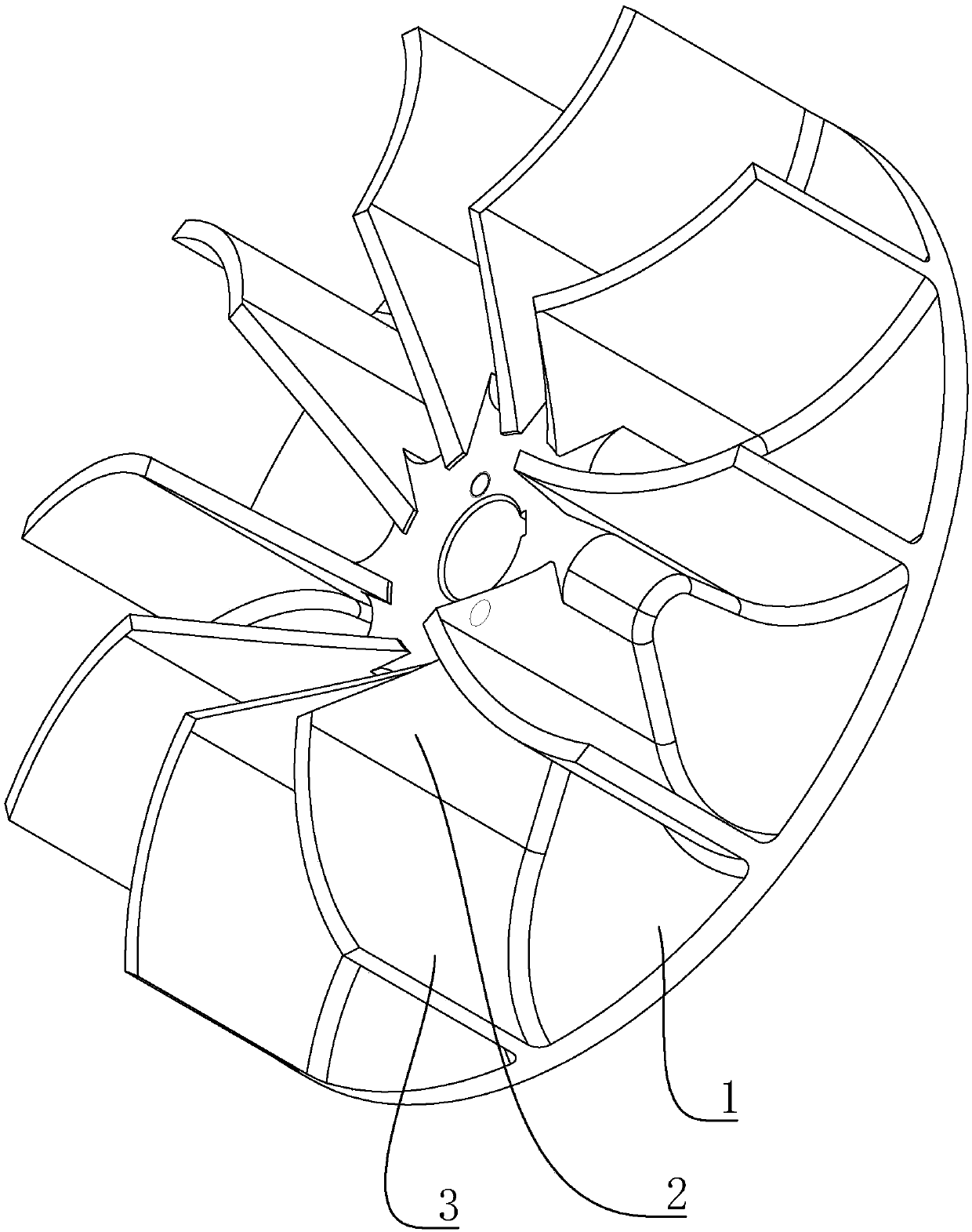
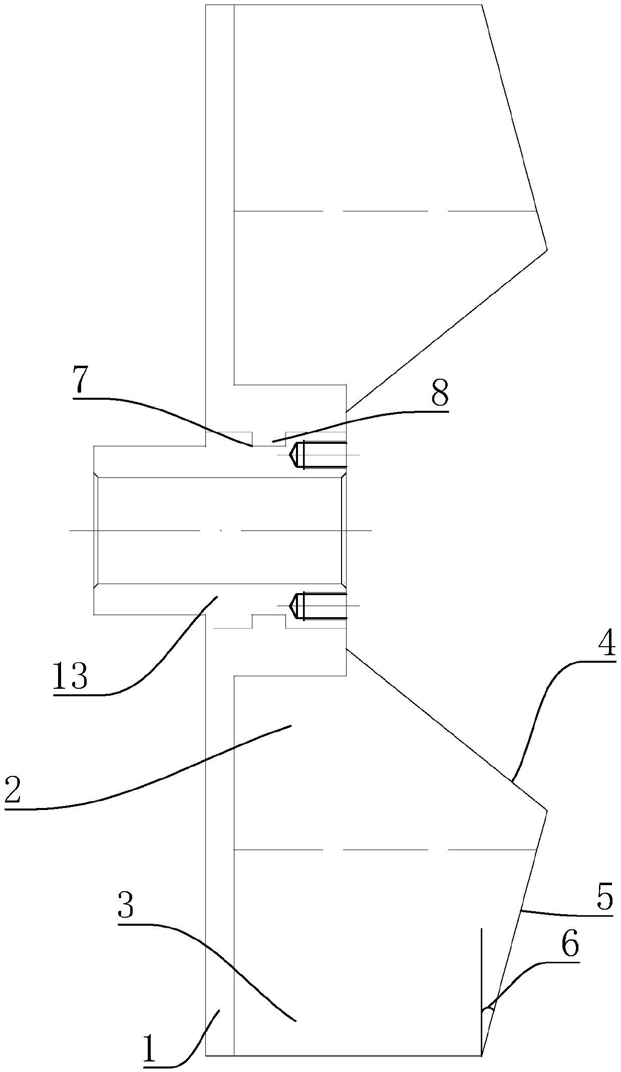
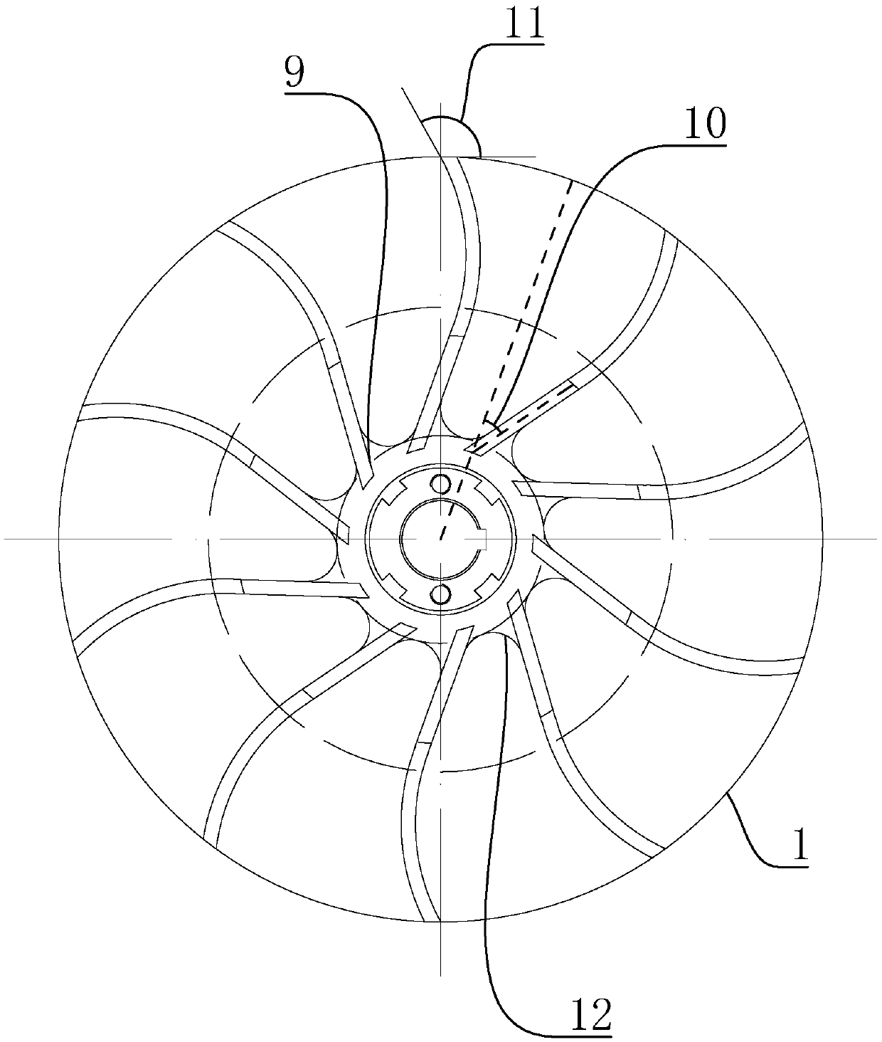
The invention discloses a rear-bending type impeller. The rear-bending type impeller comprises a a chassis, wherein a plurality of blades are arranged on the upper surface of the chassis, and the blades are arranged in an array mode through the central circumference of the chassis. Each blade comprises a flat plate and an arc plate connected with one side of the flat plate, and the arc plate is arranged on one side away from the middle of the chassis. A first inclined section and a second inclined section connected with the first inclined section are arranged on the top surface of each blade,the first inclined section is arranged on the top surface of the flat plate, the first inclined section is arranged at one end close to the center of the chassis, and the height of the first inclination is gradually increased from the middle of the chassis to the outer side of the chassis. The second inclined section is connected to one side of the highest point of the first inclined section, theheight of the second inclined section is gradually reduced towards the edge of the outer side of the chassis, a first included angle is formed between the upper surface of the second inclined sectionand the surface of the chassis, the outer side surfaces of the first inclined section and the second inclined section are both coplanar with the outer side surface of each blade. According to the rear-bending type impeller, the problems that a traditional centrifugal impeller is single in structure and cannot adjust wind speed and wind volume conveniently are solved.

Description

technical field [0001] The invention relates to an impeller, especially a backward curved impeller. Background technique [0002] At present, the design method of the fan centrifugal impeller is to adopt a single straight blade or a single arc flow design. Such a serialized single design will cause the performance of the fan to change too much, and it is inconvenient to control the wind speed and air volume. Traditional impeller blades and impellers are all processed by steel plates, and the blades are prone to bending and deformation, which makes it difficult to guarantee the performance of the fan, and the performance of the blades processed by single plate is poor; the impeller is processed by welding, the processing accuracy is difficult to guarantee, and the manufacturing cost is too high. High, low working efficiency, difficult to guarantee the performance of the fan; the whole impeller is welded with steel plate material, and it is easy to generate sparks due to stati...

Claims


Application Information

Patent Timeline
Patent Type & Authority Applications(China)
IPC IPC(8): F04D29/28F04D29/30F04D29/02
CPCF04D29/023F04D29/281F04D29/30
Inventor 付观井
Owner FOSHAN CITY NANHAI POPULA FAN
Learn More