a pressure reducing valve

A technology of pressure reducing valve and valve body, applied in valve device, safety valve, balance valve and other directions, can solve the problems of high manufacturing cost, pressure reduction and pressure reduction, complex structure, etc., and achieve long service life, reliable pressure reduction effect, Small size effect

Active Publication Date: 2020-12-04
BEIJING RES INST OF MECHANICAL & ELECTRICAL TECH
View PDF9 Cites 0 Cited by
  • Summary
  • Abstract
  • Description
  • Claims
  • Application Information

AI Technical Summary

Problems solved by technology

[0002] The pressure reducing valve is a valve that reduces the inlet pressure to a certain required outlet pressure through adjustment, and relies on the energy of the medium itself to keep the outlet pressure automatically stable. By changing the throttling area, the flow rate and fluid kinetic energy are changed, resulting in different pressure loss, so as to achieve the purpose of decompression, and then rely on the adjustment of the control and regulation system to keep the pressure behind the valve constant within a certain error range. With the increasing market demand for pressure relief valves, pressure relief valves There are also more and more types of pressure reducing valves in the prior art. The air inlet, air outlet and valve core are in a relatively vertical spatial position, the structure is complex, the manufacturing cost is high, and it is not easy to operate, and the existing pressure reducing valves generally They are all in a state of static pressure. If the air source pressure is in a dynamic change process, it is impossible to stabilize and decompress in a short time.

Method used


Image

  • a pressure reducing valve
  • a pressure reducing valve
  • a pressure reducing valve

Examples


Embodiment Construction

[0019] The present invention will be described in detail below in conjunction with specific examples and accompanying drawings.

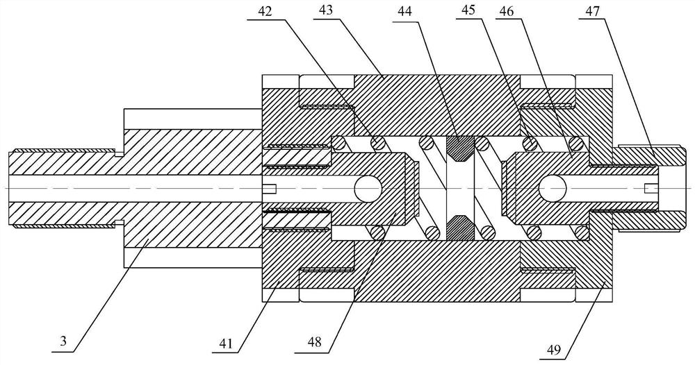
[0020] The present invention as figure 1 As shown, it includes an air inlet 41, a valve body 43, a valve core, an air outlet 49 and an adjusting bolt 47. The valve core is installed inside the valve body 43, and the two ends of the valve body 43 are respectively threaded with the air inlet 41 and the air outlet 49. , the air inlet 41 is connected to the upstream air source through the one-way valve 3 .

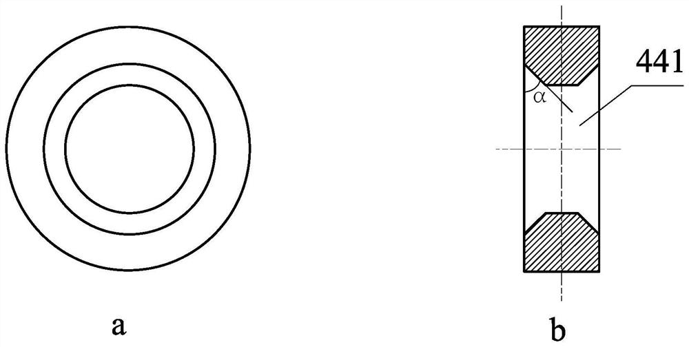
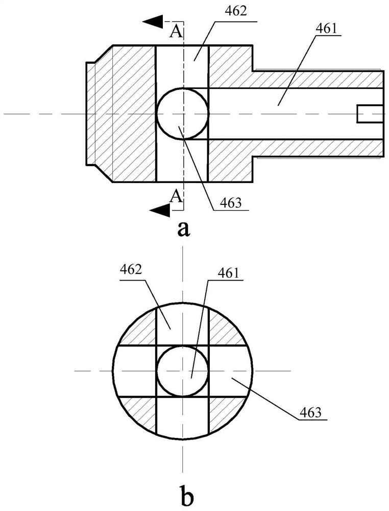
[0021] Spool such as figure 1 As shown, it is composed of an intake flow regulating rod 48, an intake spring 42, a pressure regulating orifice 44, an outlet spring 45 and an outlet flow regulating rod 46. and the air outlet spring 45 are respectively compressed on the two ends of the pressure adjustment orifice plate 44, and are respectively sleeved outside the air intake flow adjustment rod 48 and the air outlet flow adjustment rod 46. The air i...


PUM


Abstract

The invention provides a pressure reducing valve comprising an air inlet, a valve body, a valve element, an air outlet and an adjusting bolt. The valve element is installed inside the valve body, thetwo ends of the valve body are mechanically connected with the air inlet and the air outlet separately, the air inlet, the valve body, the valve element, the air outlet and the adjusting bolt are coaxial, and the valve element is composed of an air inlet flow adjusting rod, an air inlet spring, a pressure adjusting orifice plate, an outlet spring and an air outlet flow rate adjusting rod. The pressure reducing valve has the advantages that the structure is simple and compact, operation is easy, and the service life is long; and the valve element adopts full-channel straight-through design, thepressure loss is small, the flow rate is large, the volume is small, and the weight is small.

Description

technical field [0001] The invention relates to a pressure reducing valve, which belongs to the technical field of straight-through pressure stabilizing and pressure reducing valves. Background technique [0002] The pressure reducing valve is a valve that reduces the inlet pressure to a certain required outlet pressure through adjustment, and relies on the energy of the medium itself to keep the outlet pressure automatically stable. By changing the throttling area, the flow rate and fluid kinetic energy are changed, resulting in different pressure loss, so as to achieve the purpose of decompression, and then rely on the adjustment of the control and regulation system to keep the pressure behind the valve constant within a certain error range. With the increasing market demand for pressure relief valves, pressure relief valves There are also more and more types of pressure reducing valves in the prior art. The air inlet, air outlet and valve core are in a relatively vertical...

Claims


Application Information

Patent Timeline
Patent Type & Authority Patents(China)
IPC IPC(8): F16K17/20F16K17/24
CPCF16K17/20F16K17/24
Inventor 姚琰方新
Owner BEIJING RES INST OF MECHANICAL & ELECTRICAL TECH
Why Eureka
Try Eureka