
Multi-channel rotating joint

A rotary joint, multi-channel technology, applied in the direction of pipe/pipe joint/pipe fitting, adjustable connection, passing element, etc., can solve the problems of large heat production, reduce the maximum speed of the rotary joint, reduce the service life, etc., to prolong the service life , simple structure, small number of effects

Pending Publication Date: 2019-04-05
宁波迈途机械科技有限公司
View PDF0 Cites 1 Cited by
  • Summary
  • Abstract
  • Description
  • Claims
  • Application Information

AI Technical Summary

Problems solved by technology

At present, the existing multi-channel rotary joints are usually provided with a plurality of conveying holes along the axial direction of the rotating shaft in the rotating shaft, and an introduction hole matched with the conveying holes is arranged on the side wall of the outer shell of the joint. The inlet holes are matched and communicated to form a conveying channel. In order to avoid leakage and mixing of different media during the conveying process (that is, to realize the sealing between each conveying channel), multiple rotary oil seals are usually set between the rotating shaft and the outer shell to realize The separation between adjacent conveying passages, however, the setting of so many rotary oil seals results in a large friction force between the rotating shaft and the outer casing, which greatly reduces the maximum rotational speed that the rotary joint can withstand. At the same time, due to the high The existence of friction makes the rotary joint generate a lot of heat during the working process, and the overall temperature is high during the entire use process, which greatly reduces the service life of the product

Method used


Image

  • Multi-channel rotating joint
  • Multi-channel rotating joint
  • Multi-channel rotating joint

Examples


Embodiment Construction

[0018] The present invention will be further described in detail below in conjunction with the accompanying drawings and embodiments.

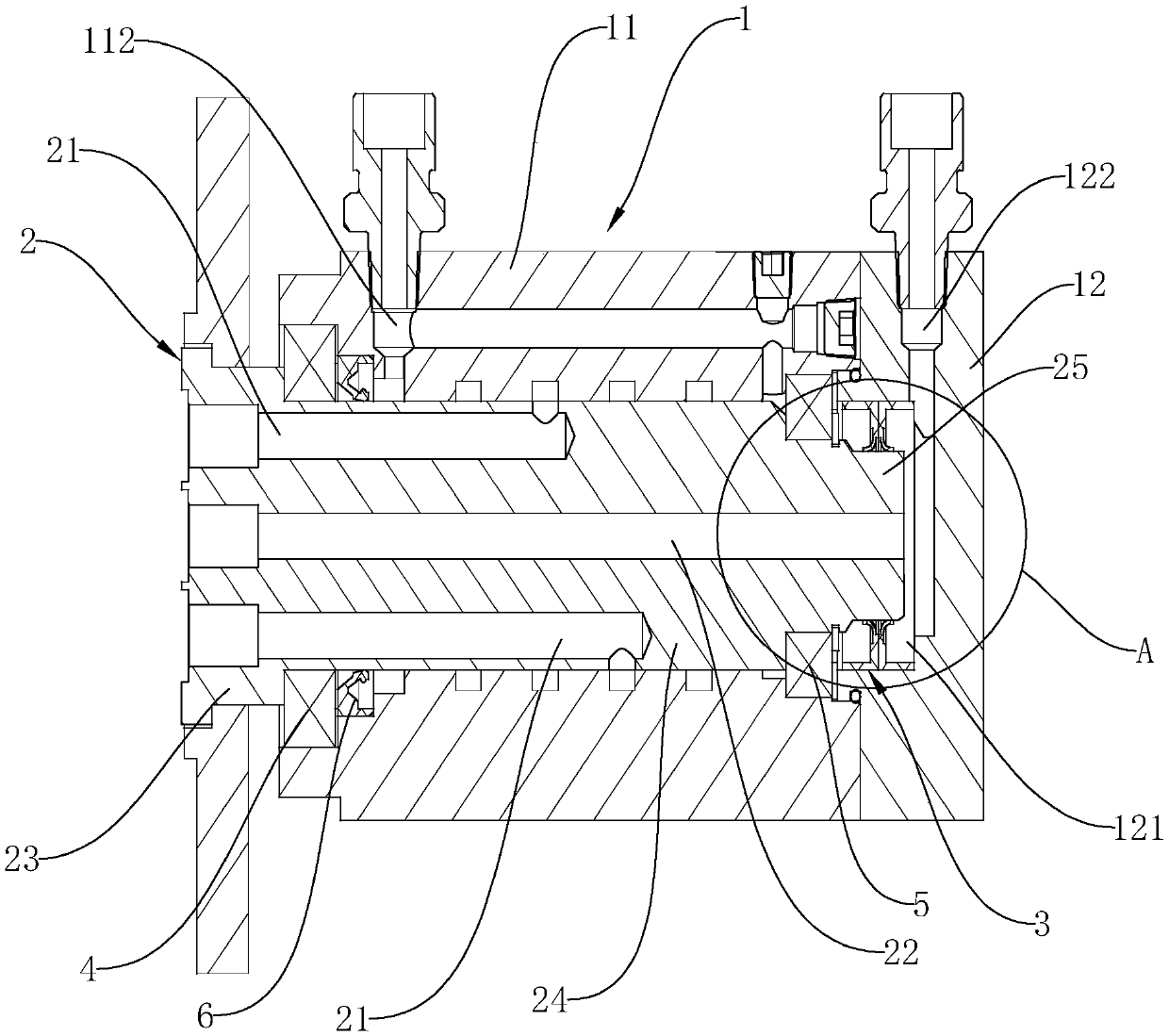
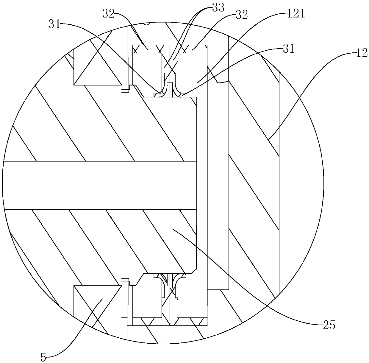
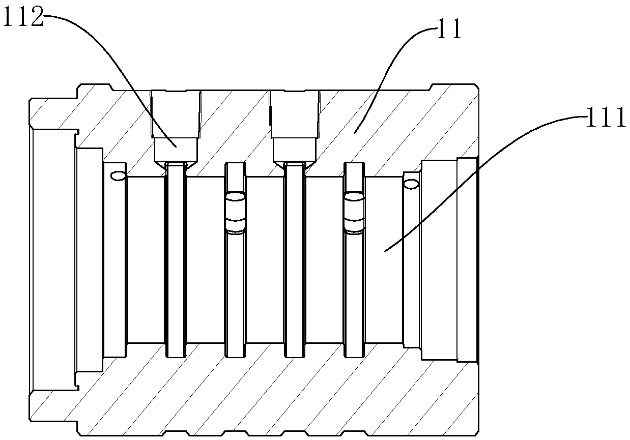
[0019] Such as Figure 1 to Figure 4 As shown, a multi-channel rotary joint includes an outer casing 1 and a rotating shaft 2. The outer casing 1 includes an outer sleeve 11 and a back cover 12 sealed and installed at the rear end of the outer sleeve 11. The outer sleeve 11 is provided with a front and rear through An installation chamber 111 for installing the rotating shaft 2, the rotating shaft 2 is rotatably arranged in the installation chamber 111 and the front end of the rotating shaft 2 protrudes from the installation chamber 111;

[0020] A plurality of first conveying holes 21 are arranged in the rotating shaft 2, and the first conveying holes 21 are blind holes arranged along the direction of the central axis of the rotating shaft 2 from the front end surface of the rotating shaft 2, and are arranged on the side wall of the outer sle...


PUM


Abstract

The invention discloses a multi-channel rotating joint. The multi-channel rotating joint comprises an outer shell and a rotating shaft. The multi-channel rotating joint is characterized in that the outer shell comprises an outer sleeve and a rear cover; a mounting cavity is formed in the outer sleeve; the rotating shaft is rotatably arranged in the mounting cavity and internally provided with multiple first conveying holes; the side wall of the outer sleeve is provided with a first guiding-in hole matched with the first conveying holes, and the first conveying hole in the corresponding position communicates with the first guiding-in hole to form a first conveying channel; the rotating shaft is internally provided with a second conveying hole which is through in the front-back direction; the front end face of the rear cover is provided with a mounting sunken cavity; the rear end of the rotating shaft extends into the mounting sunken cavity; the rear cover is provided with a second guiding-in hole, and the second guiding-in hole communicates with the second conveying hole to form a second conveying channel; and a rotating shaft seal is arranged between the rear end of the rotating shaft and the mounting sunken cavity. The multi-channel rotating joint has the advantages that the structure is simple, and the cost is low; the influence on the rotating speed of the rotating shaft issmall while the sealing performance is guaranteed; and thus, the service life is effectively prolonged.

Description

technical field [0001] The invention relates to a rotary joint, in particular to a multi-channel rotary joint. Background technique [0002] The rotary joint usually includes an outer casing and a rotating shaft arranged in the outer casing, which is mainly used to introduce the oil circuit or the air circuit into the high-speed rotating rotary mechanism to realize the control and distribution of the oil circuit or the gas circuit in the rotary mechanism. Rotary joints can be divided into single-channel rotary joints and multi-channel rotary joints according to the number of conveying channels, where multi-channel rotary joints can be used to introduce two or more different media into the high-speed rotating shaft through different channels. At present, the existing multi-channel rotary joints are usually provided with a plurality of conveying holes along the axial direction of the rotating shaft in the rotating shaft, and an introduction hole matched with the conveying hole...

Claims


Application Information

Patent Timeline
Patent Type & Authority Applications(China)
IPC IPC(8): F16L27/093
CPCF16L27/093
Inventor 潘峰
Owner 宁波迈途机械科技有限公司
Learn More