
A gas injection engine

An engine and gas technology, applied in gas turbine installations, machines/engines, mechanical equipment, etc., can solve the problems of high manufacturing cost, large axial size of the engine, and difficult impeller design and manufacturing, and achieve high gas supply pressure and mechanical Efficiency and compressor working efficiency, the effect of improving mechanical efficiency and compressor working efficiency

Active Publication Date: 2019-10-11
ANHUI UNIVERSITY OF TECHNOLOGY
View PDF5 Cites 0 Cited by
  • Summary
  • Abstract
  • Description
  • Claims
  • Application Information

AI Technical Summary

Problems solved by technology

However, the combustion chamber pressure of existing gas engines depends on the speed and blade shape of the compressor impeller. The engine usually needs to use multi-stage impellers to boost the pressure, so the axial size of the engine is large, the impeller design and manufacture are difficult, and the manufacturing cost is high. shortcoming

Method used


Image

  • A gas injection engine
  • A gas injection engine
  • A gas injection engine

Examples


Embodiment Construction

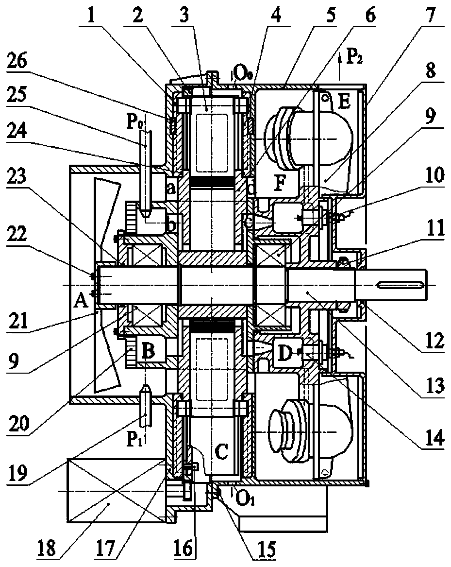
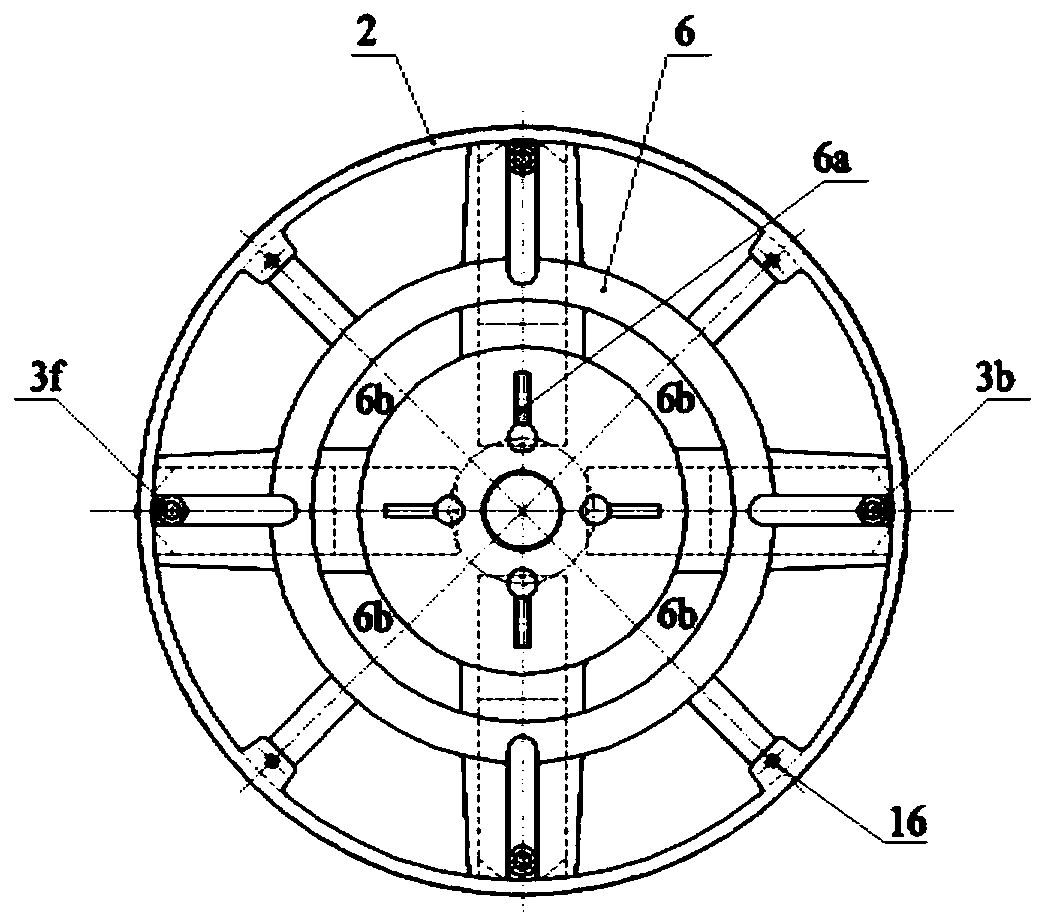
[0037] The present invention provides a gas injection engine, which comprises a left cam 1, a plunger assembly 3, a right cam 4, a rotating cylinder 6, a large ring gear 2, a central shaft 13, a left box 17, a left end cover 20, and an impeller 21 , Starter motor 18, inner nozzle 25, outer nozzle 19, right casing 5, right end cap 7, conductive ring 10, turntable 8, spark plug 14, guide tube 29, spool 28 and spring 27.

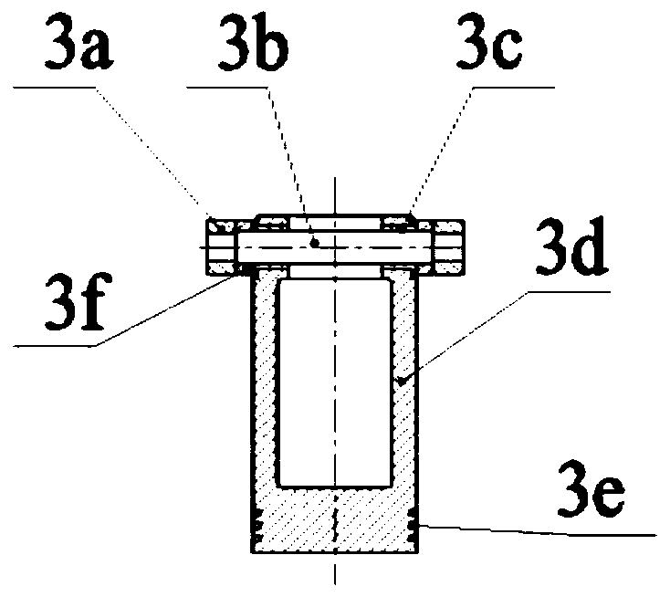
[0038] figure 2 It is an assembly diagram of the plunger assembly in the engine of the present invention. One end of the plunger 3d is hinged with the short shaft 3b through the bearing bush 3c, and the other end is equipped with a sealing ring 3e. The bushing 3f is vacantly sleeved on the short shaft 3b. The roller 3a is in interference connection with the shaft end of the short shaft 3b. Two bushings 3f, two bearing bushes 3c and two rollers 3a are arranged symmetrically on both sides of the axis of the plunger 3d, forming the radial movement unit of the co...


PUM


Abstract

The invention discloses a gas-jet engine and belongs to the technical field of gas engine equipment. The engine comprises a gas compression rotor, a gas jet rotor, a base, a starting motor, a fuel injection pipe and an igniting device; the gas compression rotor is positioned in a left chamber of the base; the gas jet rotor is positioned in a right chamber of the base; the rotation axes of the gascompression rotor and the gas jet rotor are overlapped and the gas compression rotor and the gas jet rotor rotate synchronously; the gas compression rotor is used for sucking air from the axial direction to make the air be mixed with fuel or gas from the outlet of the fuel injection pipe; a plunger on the gas compression rotor is used for compressing the mixture into a main combustion chamber of the gas jet rotor to realize combustion so as to generate high-temperature and high-pressure gas; the high-temperature and high-pressure gas is increased and pressurized by a jet flow valve arranged onthe gas jet rotor and is then injected out of a tangential nozzle arranged on the gas jet rotor, therefore the aerodynamic force generated can push a rotor to rotate and output power. The gas-jet engine disclosed by the invention has the characteristics of being compact in axial structure, high in work reliability, wide in speed regulation range, large in output torque and the like.

Description

Technical field: [0001] The invention belongs to the technical field of gas engine equipment, and in particular relates to a gas injection engine. Background technique: [0002] Gas engines usually require a compressor to generate high-pressure air, which is mixed with fuel and combusted in a fixed combustion chamber to generate high-temperature and high-pressure airflow. The power required by the compressor is generated through the nozzle and power turbine, and at the same time it outputs strong thrust or torque. Existing gas engines usually use axial-flow compressors as their compressors. The technology is mature, and it has the characteristics of compact radial structure, good stability, and long service life. It is widely used in fields such as automobiles, aircraft, and mobile robots. However, the combustion chamber pressure of existing gas engines depends on the speed and blade shape of the compressor impeller. The engine usually needs to use multi-stage impellers to b...

Claims


Application Information

Patent Timeline
Patent Type & Authority Patents(China)
IPC IPC(8): F04B27/047F02C3/055F02C3/32
Inventor 张玉华陈林华王孝义熊亮
Owner ANHUI UNIVERSITY OF TECHNOLOGY
Learn More