Deflector plate type annular guide pipe for ship

An annular duct and deflector technology, which is applied in ship propulsion, ship parts, ship construction, etc., can solve the problems of simple technical configuration of wake compensation duct, unstable internal flow field of the duct, and insignificant energy saving effect. Good energy saving effect, energy saving effect and vibration performance improvement, simple processing effect

Pending Publication Date: 2018-05-04
CSIC SHANGHAI MARINE ENERGY SAVING TECH DEV CO LTD
View PDF5 Cites 2 Cited by
  • Summary
  • Abstract
  • Description
  • Claims
  • Application Information

AI Technical Summary

Problems solved by technology

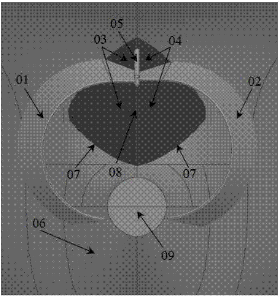
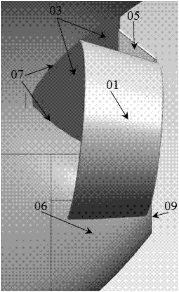
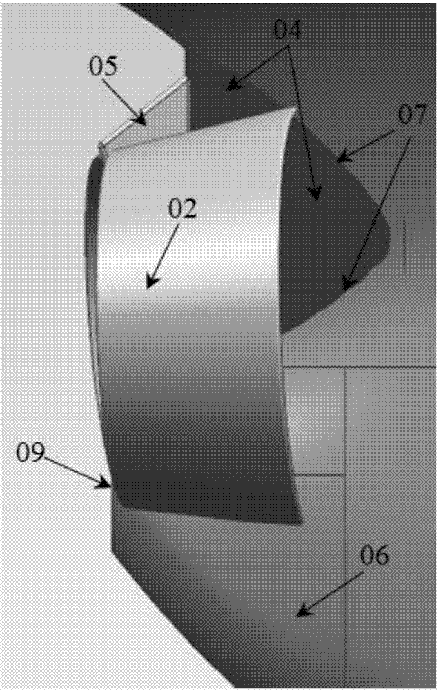
[0008] The purpose of the present invention is to solve the problems of simple configuration of the existing wake compensation duct technology, insufficient stability of the flow field inside the duct, and insignificant energy-saving effect, etc., and provide a A marine deflector-type annular duct, through the deflector guides the flow field inside the duct above the outlet of the tail shaft, and the annular duct rectifies the flow field on the left and right sides above the propeller shaft, making the flow field entering the propeller more uniform and stable. The propulsion efficiency of the propeller and the thrust on the annular duct are improved, the speed is increased, and the vibration performance of the stern is effectively improved at the same time

Method used


Image

  • Deflector plate type annular guide pipe for ship
  • Deflector plate type annular guide pipe for ship
  • Deflector plate type annular guide pipe for ship

Examples


Embodiment

[0035] A rapid model test of different energy-saving ducts installed on a 5000-ton cargo ship, ordinary ducts without deflectors without any energy-saving devices (see Figure 8 ) and install the deflector type annular duct of the present invention (see Figure 9 And the test result of table 1), as shown in table 2 to table 4. From the comparison of Table 2 and Table 3, it can be seen that at the same speed (such as 12.0kn), the propulsion efficiency η of installing ordinary ducts (without deflectors on the left and right sides) is higher than that of installing annular ducts without deflectors. DS Slightly increased, effective power P ES Almost unchanged, the energy-saving effect ΔPd is 2.5%. From the comparison of Table 2 and Table 4, it can be seen that at the same speed (for example, at 12.0kn), after the deflector-type annular duct is installed, the thrust deduction t and wake fraction w of the hull are both smaller than those of the non-deflector-type annular duct. , ...


PUM


Abstract

The invention provides a ship hydrodynamic energy-saving device installed on the front of the exit of a hull tail shaft. The ship hydrodynamic energy-saving device is characterized by comprising a larboard flow guide pipe, a starboard flow guide pipe, a larboard deflector, a starboard fluid deflector and an intermediate reinforcement structure, wherein the larboard flow guide pipe and the starboard flow guide pipe are arranged on the two sides of a hull tail part on the front of the exit of a ship tail shaft, the lower ends of the flow guide pipes are directly connected to a hull, the upper ends of the flow guide pipes are connected to the deflectors and the intermediate reinforcement structure, and the deflectors and the intermediate reinforcement structure are connected to the hull. A deflector plate type annular guide pipe of the invention can effectively improve the wake flow field of a ship, the surface of the guide pipe can generate thrust force, the output power of a host machine at the same speed is reduced, the vibration performance of a propeller is improved, and better energy saving effect is achieved. The device has a simple and reliable structure, is easy to install and maintain, has a good energy-saving effect, and is easy to install on an existing ship.

Description

technical field [0001] The invention relates to a hydrodynamic energy-saving attachment device installed in front of a stern propeller and can effectively reduce the output power of a ship's main engine, in particular to a marine deflector-type annular conduit. Background technique [0002] 90% of the world's international trade goods are transported by ships. The resulting greenhouse gas emissions and environmental pollution have become increasingly prominent, and environmental protection regulations have become increasingly stringent. At the same time, fuel expenditures account for a major proportion of ship operating costs. The urgent needs of scientific research institutes, design institutes, shipyards and shipowners, there is a huge market for ship hydrodynamic energy-saving attachment devices in the shipbuilding industry. The current hydrodynamic energy-saving devices in front of the propeller include wake compensation ducts, rectifying fins, pre-rotation fins plus ful...

Claims


Application Information

Patent Timeline
Patent Type & Authority Applications(China)
IPC IPC(8): B63H5/15
CPCB63H5/15
Inventor 陈雷强黄振宇黄树权吴赞夏灏超李鹏程严周广张宁
Owner CSIC SHANGHAI MARINE ENERGY SAVING TECH DEV CO LTD
Why Eureka
Try Eureka