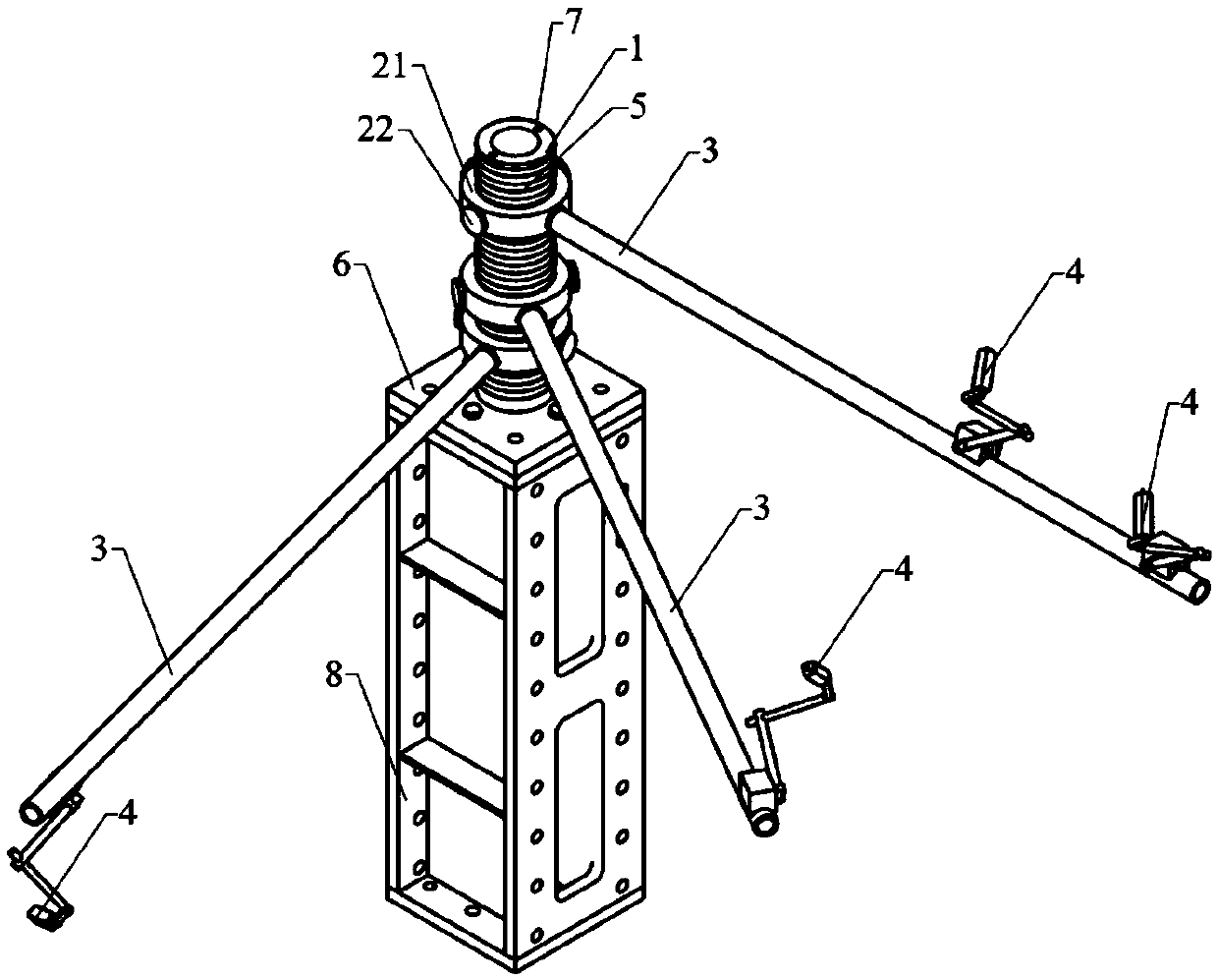
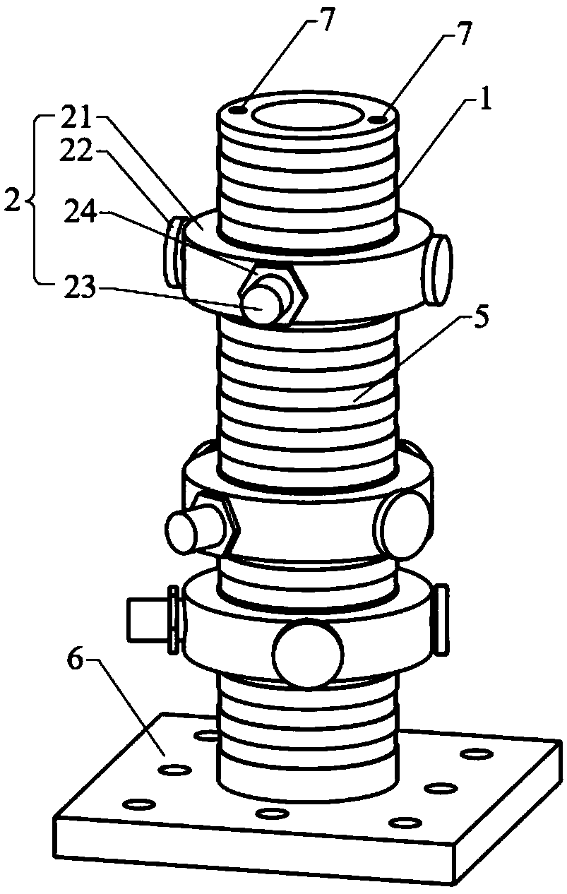
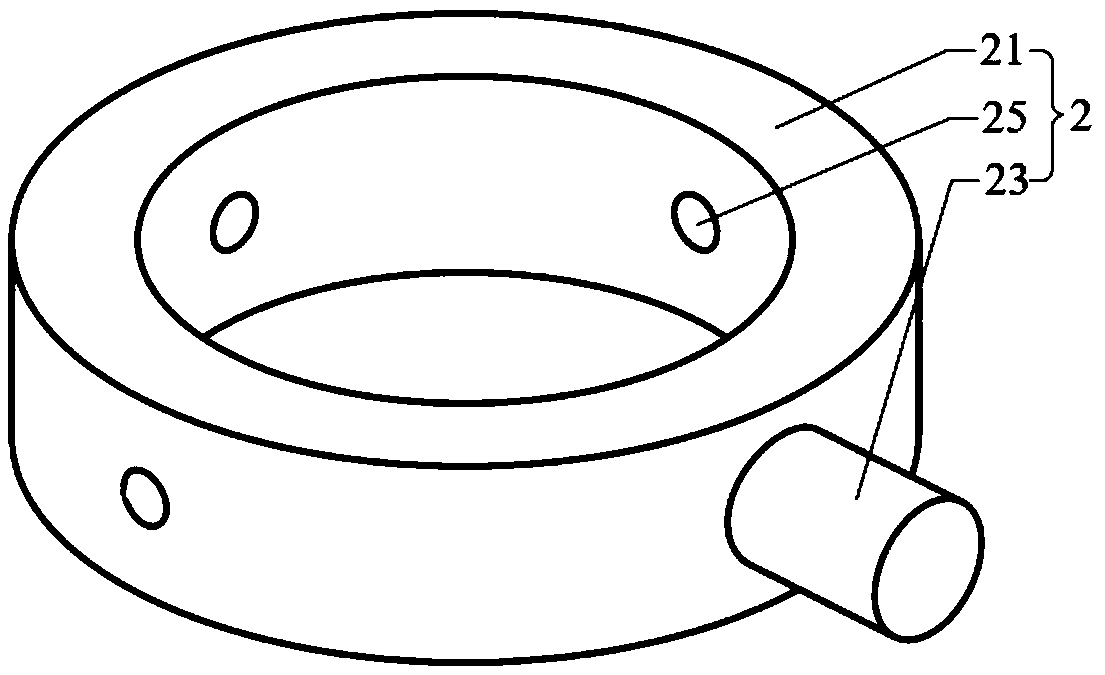
Static force test device and sensor mounting seat

A technology of sensors and mounts, which is applied in the field of sensors, can solve problems such as blind spots in the structure detection of test pieces, and achieve the effect of improving the flexibility of use and expanding the installation range

Active Publication Date: 2019-04-05
NORTHWESTERN POLYTECHNICAL UNIV
View PDF6 Cites 2 Cited by
  • Summary
  • Abstract
  • Description
  • Claims
  • Application Information

AI Technical Summary

Problems solved by technology

[0006] Another object of the present invention is to provide a static test device, which solves the problem of detection blind spots in the structure of the test piece in the existing device

Method used


Image

  • Static force test device and sensor mounting seat
  • Static force test device and sensor mounting seat
  • Static force test device and sensor mounting seat

Examples


Embodiment Construction

[0028] Example embodiments will now be described more fully with reference to the accompanying drawings. Example embodiments may, however, be embodied in many forms and should not be construed as limited to the examples set forth herein; rather, these embodiments are provided so that this disclosure will be thorough and complete, and will fully convey the concept of example embodiments to the Those skilled in the art. The described features, structures, or characteristics may be combined in any suitable manner in one or more embodiments. In the following description, numerous specific details are provided in order to give a thorough understanding of embodiments of the present disclosure. However, one skilled in the art will appreciate that the technical solutions of the present disclosure may be practiced without one or more of the specific details, or that other methods, materials, devices, etc. may be employed. In other instances, well-known technical solutions have not be...


PUM


Abstract

The invention provides a static force test device and a sensor mounting seat. The sensor mounting seat comprises a supporting column, sliding ring assemblies and connecting pieces. Each sliding ring assembly comprises a sliding ring and a positioning piece, wherein the sliding ring is slidably arranged on the supporting column in a sleeving mode and can rotate around the axis of the supporting column, and the positioning piece is arranged on the sliding ring, and can abut against the supporting column or be separated from the supporting column. The connecting pieces are connected to the sliding rings and can be connected with sensors. In the installing process, the sensors can be installed at any height of the supporting column by sliding the sliding rings; and by rotating the sliding rings, the sensors can be mounted at any angle in the circumferential direction of the supporting column. Therefore, the sensor mounting seat can enlarge the mounting range of the sensors and improve theuse flexibility of the sensors.

Description

technical field [0001] The invention relates to the technical field of sensors, in particular to a static test device and a sensor mounting seat. Background technique [0002] In the static test, in order to study the change of the test piece under a given load, it is necessary to arrange sensors on the key points of the test piece structure for detection. [0003] In the prior art, the sensors are arranged using support columns provided with mounting holes. The installation holes are distributed at intervals along the height direction of the support column, so that the sensor can be installed at different heights of the support column. However, the above-mentioned sensors cannot be installed between adjacent installation holes on the support column, resulting in a small installation range, and thus there is a detection blind spot in the structure of the test piece. [0004] It should be noted that the information disclosed in the above background technology section is onl...

Claims


Application Information

Patent Timeline
Patent Type & Authority Applications(China)
IPC IPC(8): F16M13/02G01M13/00
CPCF16M13/02G01M13/00
Inventor 王心美李磊岳珠峰
Owner NORTHWESTERN POLYTECHNICAL UNIV
Why Eureka
Try Eureka