Building pile foundation

The invention relates to a technology for building piles and pile foundations, which is applied to building pile foundations. field, to achieve the effect of improving efficiency, accelerating the speed of digging down, and increasing the scope

Inactive Publication Date: 2021-03-12
王华清
View PDF7 Cites 1 Cited by
  • Summary
  • Abstract
  • Description
  • Claims
  • Application Information

AI Technical Summary

Problems solved by technology

[0004] Aiming at the deficiencies of the prior art, the present invention provides a construction pile foundation, which can increase the contact area between the metal reinforcing rod installed in the pile foundation and the poured cement, increase the firmness of the pile foundation, and can dig the foundation pit while digging The pile foundation is placed inside the foundation pit, which reduces the steps of pile foundation filling, improves the efficiency of pile foundation construction, reduces the difficulty of digging the foundation pit, and does not need to consider the adaptation of the size of the foundation pit and the pile foundation, and can properly Dig out the foundation pit with the same size as the pile foundation, which is convenient for the pile foundation to be fixed after being placed in the foundation pit, and reduces the workload when pre-excavating the foundation pit

Method used


Image

  • Building pile foundation
  • Building pile foundation
  • Building pile foundation

Examples


Embodiment 1

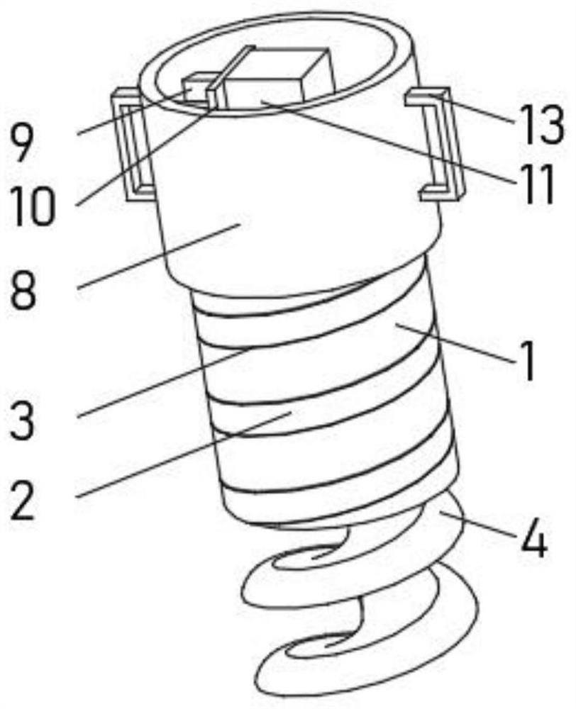
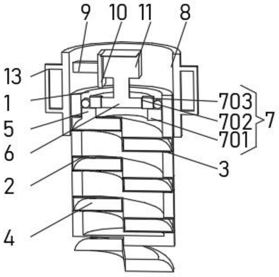
[0028] see Figure 1-2 , the present invention provides a technical solution: a construction pile foundation, comprising a pile foundation frame 1, a spiral frame 2 is installed on the inner wall of the pile foundation frame 1, the spiral frame 2 runs through the pile foundation frame 1, and the pile foundation frame 1 The outside of the frame 1 is provided with an installation groove 3 that is compatible with the spiral outer frame 2. Both ends of the spiral outer frame 2 are designed with openings. Both ends extend to the outside of the spiral outer frame 2, the top end of the rotary soil knife 4 is fixedly connected with a positioning disc 6 through a connecting block 5, and the inner wall of the pile foundation outer frame 1 is located below the positioning disc 6 and a positioning device 7 is installed One end of the bottom of the rotary soil knife 4 extends to the outside of the pile foundation frame 1, and the top end of the pile foundation frame 1 is provided with a po...

Embodiment 2

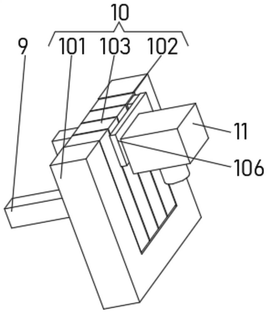
[0033] see Figure 1-4 , the present invention provides a technical solution: on the basis of Embodiment 1, the limiting plate 10 includes a vertical plate 101, one side of the vertical plate 101 is fixedly connected with the connecting rod 9, and a track is provided in the middle position of one side of the vertical plate 101 The groove 102 and the two sides of the track groove 102 are evenly equipped with lifting plates 103 , the lifting plates 103 are slidably connected, and the lifting plate 103 is slidably connected with the inner wall of the track groove 102 .

[0034] One side of the track groove 102 and the lifting plate 103 is provided with a longitudinal chute 104, and one end of the bottom of one side of the lifting plate 103 is fixedly connected with a slider 105, and one end of the slider 105 extends to the inside of the longitudinal chute 104 and is connected with the longitudinal chute. The inner wall of the groove 104 is slidingly connected.

[0035] The lifti...

Embodiment 3

[0038] see Figure 1-4 , the present invention provides a technical solution: on the basis of Embodiment 1, a filling device 12 is evenly installed on the top of the spiral outer frame 2, and the filling device 12 includes a filling hole 121, and the filling hole 121 is opened on the top of the spiral outer frame 2, One side of the inner wall of the filling groove 121 is rotatably connected with an isolation plate 122, the bottom of the isolation plate 122 is equipped with a metal block 123, and the bottom of the isolation plate 122 is provided with a metal installation groove suitable for the metal block 123. A magnet block 124 is mounted on the top close to the filling hole 121 , and a magnet installation slot matching the magnet block 124 is opened on the inner top of the spiral outer frame 2 .

[0039] During use, the drilling motor 11 drives the rotary soil cutter 4 to rise along the spiral outer frame 2. When the rotary soil cutter 4 gradually moves to the outside of the...


PUM


Abstract

The invention discloses a building pile foundation, and relates to the technical field of buildings. The building pile foundation comprises a pile foundation outer frame, wherein a spiral outer frameis mounted on the inner wall of the pile foundation outer frame, the spiral outer frame penetrates through the pile foundation outer frame, a mounting groove matched with the spiral outer frame is formed in the outer side of the pile foundation outer frame, a soil rotating cutter is slidably connected to the interior of the spiral outer frame, and the two ends of the soil rotating cutter extend tothe outer part of the spiral outer frame. According to the building pile foundation, the contact area of metal reinforcing rods installed in the pile foundation and poured cement can be increased, the firmness degree of the pile foundation is increased, the pile foundation can be placed into a foundation pit while the foundation pit is dug, the pile foundation landfill step is reduced, the pile foundation construction efficiency is improved, the foundation pit digging difficulty is reduced, the foundation pit with the same size as the pile foundation can be dug out properly without considering the size adaptation problem of the foundation pit and the pile foundation, the pile foundation can be fixed conveniently after being placed in the foundation pit, and the workload of pre-digging thefoundation pit is reduced.

Description

technical field [0001] The invention relates to the technical field of construction, in particular to a construction pile foundation. Background technique [0002] The building pile foundation is used to drive into the building ground, and the interior is cemented, and the supporting pile body is formed after the cement dries. The current building pile body is generally a hollow structure, and the hollow structure is composed of more than one piece. The substrates are spliced ​​together, and then the cavities formed by splicing are poured with cement. [0003] Chinese invention CN109137890A discloses a building foundation pile, which includes a frame-shaped hollow foundation pile spliced ​​by four base plates. There is a square pouring cavity in the middle of the foundation pile, and the bottom of the four base plates can be destroyed. A hollow plate is fixedly installed on the inner side of the four base plates. There is a hollow hollow cavity inside the hollow plate. More...

Claims


Application Information

Patent Timeline
Patent Type & Authority Applications(China)
IPC IPC(8): E02D27/12
CPCE02D27/12
Inventor 王华清
Owner 王华清
Why Eureka
Try Eureka