Wall hanging fixture

A fixture and foundation surface technology, which is applied in the direction of supporting machines, mechanical equipment, machine tables/brackets, etc., can solve the problems of difficult to ensure the installation position and the inability of the display body to fit perfectly with the wall, so as to achieve stable and accurate hanging. precise position effect

Active Publication Date: 2019-04-05
HKC CORP LTD +1
6 Cites 0 Cited by

AI-Extracted Technical Summary

Problems solved by technology

[0003] The purpose of the present invention is to provide a wall hanging fixture to solve the technical problem that it is difficult to ensu...

Method used

Optionally, please refer to Fig. 1 and Fig. 3, as a kind of embodiment of wall-hanging jig 1 provided by the present invention, above-mentioned jig body 11 comprises substrate 111 and thickening part 112, and substrate 111 is flat plate , the substrate 111 has a first surface 1111 and a second surface 1112 oppositely arranged, the first surface 1111 is set to be attached to the base surface 2, the engaging portion 12 is provided on the substrate 111, and the thickening portion 112 is protruded on the second surface 1112 , the calibration component 13 is disposed on the thickened portion 112 . In this embodiment, through the arrangement of the base plate 111 and the thickened part 112, the positioning of the engaging part 12 and the protrusion 3 is ensured. At the same time, the thickened part 112 provides an installation platform for the correction component 13, preventing the correction component 13 from being corrected. The interference of the installation of the engaging part 12.
Optionally, please refer to Fig. 2, as a kind of embodiment of the wall-mounted fixture 1 provided by the present invention, above-mentioned thickening part 112 is provided with two hanging hammers 131 and two grooves 115, two hanging hammers 131 Distributed along the first direction X, and the two hanging weights 131 are staggered from each engaging portion 12 , and the two grooves 115 correspond to the two grooves 115 respectively. In this embodiment, the calibration accuracy of the wall-hanging fixture 1 is higher through the arrangement of the two hanging hammers 131 .
Optionally, please refer to Fig. 3 and Fig. 4, as a kind of embodiment of the wall-hanging jig 1 provided by the present invention, above-mentioned hanging hole 114 runs through substrate 111 and thickening portion 112, and there is a The hanging hole 114 communicates with the first avoiding groove 116 , and one end of the hanging rope 134 is provided with a stopper 135 , and the stopper 135 is set in the first avoiding groove 116 and stops at one end of the hanging hole 114 . In this embodiment, the thickened portion 112 is also provided with a second avoidance groove 117, the second avoidance groove 117 is connected between the hanging hole 114 and the groove 115, and the second avoidance groove 117 and the first avoidance groove 116 are arranged symmetrically. Through the arrangement of the first avoidance groove 116, the suspension rope is prevented from interfering with the first limiting surface 1151 or the second limiting surface 1152 when it deviates from the groove 115, thereby preventing the suspension rope from being scratched.
Wall-mounted jig 1 provided by the present invention, through the setting of jig body 11, a plurality of engaging parts 12 and correction assembly 13, jig body 11 is set to stick on the base surface 2, and a plurality of engaging parts 12 is set to engage with a plurality of protrusions 3 in one-to-o...

Abstract

The invention provides a wall hanging fixture. A plurality of locating points are arranged on a base surface and connecting pieces are installed on the locating points. The wall hanging fixture comprises a fixture body, a calibration module and a plurality of clamping parts. The fixture body is arranged to be attached to the base surface; the calibration module is arranged on the fixture body andis arranged to calibrate the position of the fixture body in a first direction and a second direction, wherein the first direction is a horizontal direction parallel to the base surface and the seconddirection is perpendicular to the base surface; and the plurality of clamping parts are arranged on the fixture body, and the plurality of clamping parts are distributed in the first direction, the plurality of clamping parts are arranged for mounting a plurality of connecting pieces, and the portion of the connecting piece exposed to the base surface is protruding. The wall-hanging fixture provided by the invention can correct the position of the fixture body in the first direction and the second direction, and provides positioning for opening the positioning point on the base surface and installing the connecting piece, thereby ensuring the positional accuracy of the connecting piece, and further enabling the part to be hung to be seamlessly adhered to the base surface.

Application Domain

Stands/trestles

Technology Topic

Structural engineering

Image

  • Wall hanging fixture
  • Wall hanging fixture
  • Wall hanging fixture

Examples

  • Experimental program(1)

Example Embodiment

[0042] In order to make the technical problems, technical solutions and beneficial effects to be solved by the present invention clearer, the following further describes the present invention in detail with reference to the accompanying drawings and embodiments. It should be understood that the specific embodiments described here are only used to explain the present invention, but not to limit the present invention.
[0043] It should be noted that when an element is referred to as being "fixed to" or "disposed on" another element, it can be directly on the other element or indirectly on the other element. When an element is referred to as being "connected to" another element, it can be directly connected to the other element or indirectly connected to the other element.
[0044] It should be understood that the terms "length", "width", "upper", "lower", "front", "rear", "left", "right", "vertical", "horizontal", "top" The orientation or positional relationship indicated by "bottom", "inner", "outer", etc. is based on the orientation or positional relationship shown in the drawings, and is only for the convenience of describing the present invention and simplifying the description, rather than indicating or implying the pointed device Or the element must have a specific orientation, be constructed and operated in a specific orientation, and therefore cannot be understood as a limitation of the present invention.
[0045] In addition, the terms "first" and "second" are only used for descriptive purposes, and cannot be understood as indicating or implying relative importance or implicitly indicating the number of indicated technical features. Thus, the features defined with "first" and "second" may explicitly or implicitly include one or more of these features. In the description of the present invention, "plurality" means two or more than two, unless specifically defined otherwise.
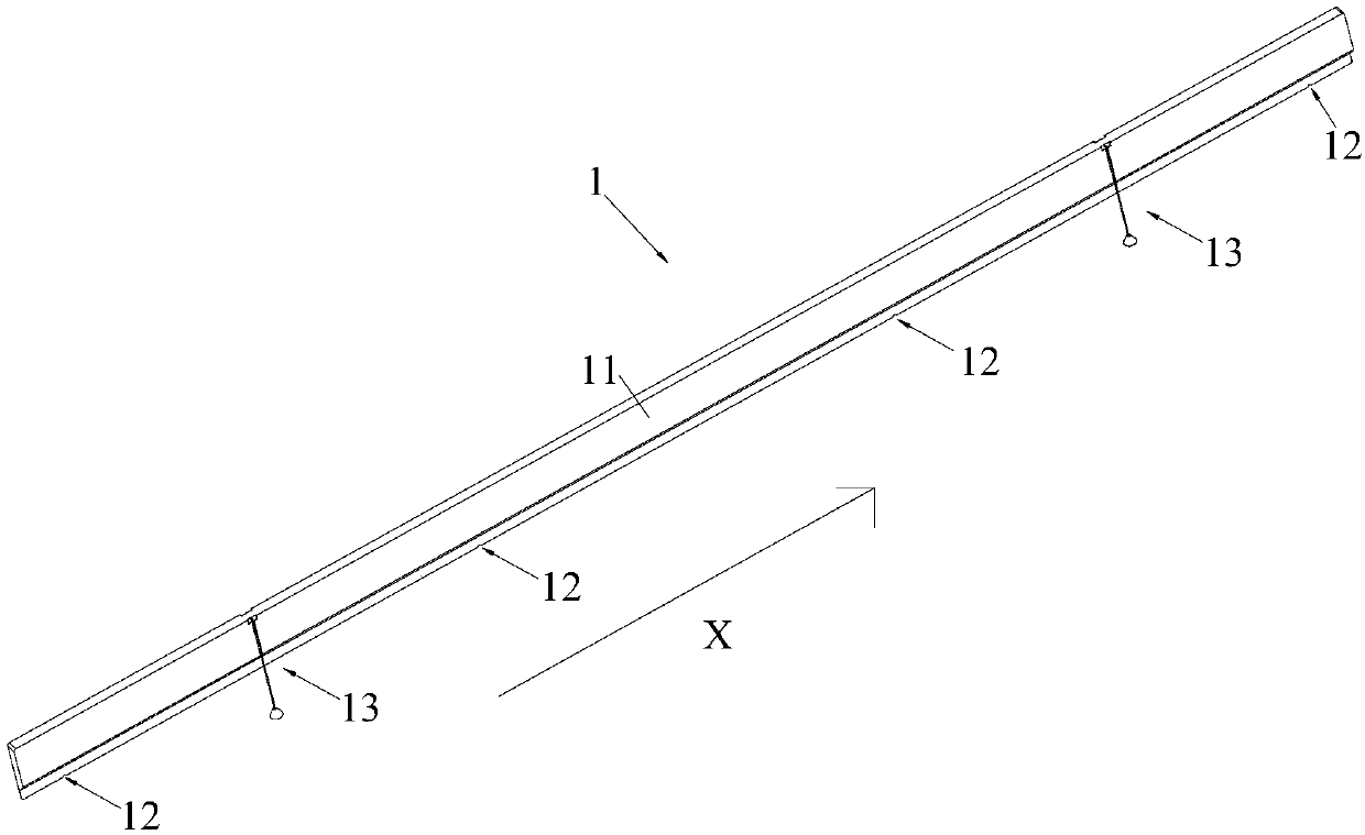
[0046] Please refer to figure 1 and figure 2 Now, the wall-hanging fixture 1 provided by the present invention will be described. The wall-hanging fixture 1 is set to open a plurality of positioning points on the base surface 2, and a connecting piece, such as a screw, is installed on the positioning point. The part of the connecting piece exposed on the base surface 2 is a protrusion 3. Determine the location of the anchor point, and then accurately install the connector. Specifically, in this embodiment, the base surface 2 may be a wall surface. Of course, in other embodiments of the present invention, according to actual conditions and specific requirements, the above-mentioned foundation surface 2 may also refer to various vertical surfaces, inclined surfaces, etc., and the above-mentioned connecting member may also be a column, a buckle, etc., here No unique restriction.
[0047] Specifically, the wall-hanging fixture 1 includes a fixture body 11, a plurality of engaging portions 12 and a calibration component 13. The jig body 11 has a block shape, and the jig body 11 is arranged to be pasted on the foundation surface 2. A plurality of engaging portions 12 are arranged on the jig body 11, the plurality of engaging portions 12 are evenly spaced along the first direction X, and the plurality of engaging portions 12 are arranged to be engaged with the plurality of protrusions 3 in a one-to-one correspondence. The calibration component 13 is provided on the fixture body 11, the calibration component 13 is configured to calibrate the position of the fixture body 11 in the first direction X, and the calibration component 13 is configured to calibrate the position of the fixture body 11 in the second direction Y, wherein, The first direction X is parallel to the base surface 2 and the second direction Y is perpendicular to the base surface 2. When using the wall-hanging fixture 1 of the present invention, the fixture body 11 is first attached to the base surface 2, and then the position of the fixture body 11 along the first direction X and the second direction Y is corrected by the correction component 13. When the position of the fixture body 11 is incorrect, readjust the position of the fixture body 11, and then use a drilling tool to open positioning points at each engagement part 12, and install connectors on the positioning points, and finally ensure the positioning points and connectors The location is precise.
[0048] The wall-mounted jig 1 provided by the present invention is provided with a jig body 11, a plurality of engaging portions 12, and a correction component 13, the jig body 11 is arranged to be attached to the base surface 2, and the plurality of engaging portions 12 are arranged as It is engaged with the plurality of protrusions 3 in a one-to-one correspondence, and the calibration component 13 is configured to calibrate the position of the fixture body 11 in the first direction X and the second direction Y, and the first direction X is in line with the distribution direction of the plurality of engaging portions 12 The same, and the first direction X is parallel to the base surface 2, and the second direction Y is perpendicular to the base surface 2. In this way, the position of the fixture body 11 along the first direction X and the second direction Y can be corrected by the wall-hanging fixture 1. This ensures that the positioning points and the connecting parts are accurately positioned, thereby ensuring that the pendant (liquid crystal TV) to be hung on the base surface 2 is stable and accurate.
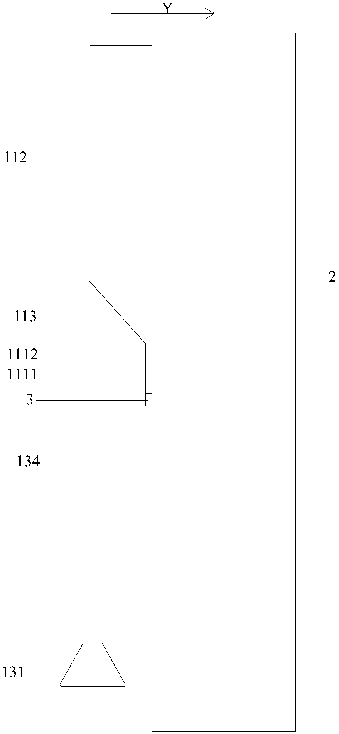
[0049] Optionally, see figure 1 and image 3 As a specific implementation of the wall-hanging fixture 1 provided by the present invention, the fixture body 11 includes a base plate 111 and a thickened portion 112. The base plate 111 is in the shape of a flat plate, and the base plate 111 has a first surface 1111 and a second surface 1111 opposite to each other. The first surface 1112 and the first surface 1111 are set to be attached to the base surface 2, the engaging portion 12 is provided on the substrate 111, the thickened portion 112 is protruded from the second surface 1112, and the correction component 13 is provided on the thickened portion 112. In this embodiment, the base plate 111 and the thickened portion 112 are provided to ensure the positioning of the engaging portion 12 and the protrusion 3, and at the same time, the thickened portion 112 provides an installation platform for the correction component 13 to prevent the correction component 13 from pairing. Interference in the installation of the engaging portion 12.
[0050] Specifically, in this embodiment, the thickened portion 112 is in the shape of a flat plate, the thickened portion 112 is located near the upper side of the substrate 111, and the left and right sides and the top side of the thickened portion 112 are aligned with the left and right sides of the substrate 111. Align side and top side. The thickened portion 112 and the second surface 1112 of the substrate 111 have a transition surface 113, and the transition surface is an inclined surface.
[0051] Optionally, see figure 2 and Figure 4 As a specific embodiment of the wall-mounted fixture 1 provided by the present invention, the plurality of engaging portions 12 are half-open grooves opened on the substrate 111, the first direction X is the horizontal direction, and the half-open grooves are opened on the substrate 111 Located at the bottom end of the vertical direction, the opening of the half-open slot faces downward. In this embodiment, the above-mentioned protrusions 3 are screws, and the above-mentioned plurality of protrusions 3 are evenly distributed in the horizontal direction, so the first direction X is the horizontal direction. In addition, the screw has a nut, in order to hang the jig body 11 It is set on the screw, and the above-mentioned engaging portion 12 is set as a half-open groove.
[0052] In other embodiments of the present invention, the protrusions 3 may be distributed along an inclined direction, and the first direction X is an inclined direction.
[0053] In other embodiments of the present invention, the above-mentioned engaging portion 12 may not be provided at the edge position of the jig body 11, at this time, the engaging portion 12 is a combination of a half-open groove and other grooves.
[0054] Optionally, in this embodiment, the diameter of the semi-open groove is set to be the same as the diameter of the protrusion 3, and the thickness of the semi-open groove in the second direction Y is set to be greater than that of the protrusion 3 in the second direction Y. The thickness is the same. In this way, when the half-open groove is buckled on the protrusion 3 after the connecting piece is installed through the wall-hanging fixture 1, the flushness of the fixture body 11 in the first direction X represents the protrusions 3 The flushness in the first direction X, the flush portion of the jig body 11 in the second direction Y represents the flushness of the protrusions 3 in the first direction X, thereby ensuring the positioning point and connection The installation accuracy of the parts.
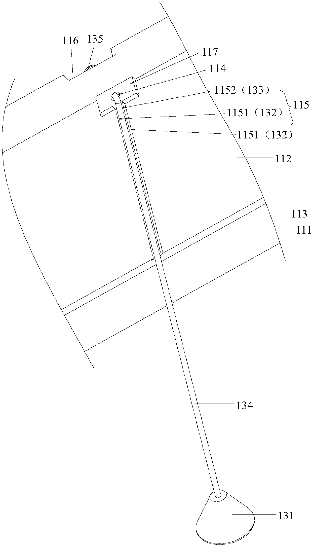
[0055] In order to accurately determine the position of the fixture body 11, optionally, please refer to image 3 The above-mentioned calibration assembly 13 includes a pendant 131, a first reading unit 132 and a second reading unit 133. The pendant 131 is hung on the thickened portion 112 by a hanging rope 134, the first reading portion 132 is provided on the thickened portion 112, and the first reading portion 132 is set to read the position of the pendant 131 along the first direction X , To correct the position of the jig body 11 to be horizontal, the second reading portion 133 is provided on the thickened portion 112, and the second reading portion 133 is set to read the position of the pendant 131 along the second direction Y to correct the jig body 11 Vertical base plane 2. In this embodiment, the hanging hammer 131 is set, because the hanging hammer 131 can always maintain a vertical position according to the principle of gravity, so that the jig body can be obtained by the position of the hanging hammer 131 in the first direction X and the second direction Y 11 along the first direction X and the second direction Y to obtain whether the jig body 11 is flush in the first direction X and the second direction Y, so as to achieve the purpose of correction. In addition, the arrangement of the first reading part 132 and the second reading part 133 facilitates reading the information of the pendant 131, which is simple and convenient to use.
[0056] Optionally, see image 3 As a specific implementation of the wall-hanging fixture 1 provided by the present invention, the thickened portion 112 is provided with a hanging hole 114, one end of the hanging rope 134 is set in the hanging hole 114, and a groove is opened directly below the hanging hole 114 115. The groove 115 extends in the vertical direction. The size of the groove 115 is adapted to the size of the lanyard 134. The groove 115 has two first limiting surfaces 1151 and a second limiting surface 1152, two first limiting surfaces The surfaces 1151 are arranged opposite to each other along the first direction X. The second limiting surface 1152 is parallel to the first surface 1111 and connected to the two first limiting surfaces 1151 respectively. The first limiting surface 1151 is the first reading portion 132, The limiting surface 1152 is the second reading portion 133. In this embodiment, by arranging the hanging hole 114 and the groove 115 on the same vertical line, the hanging rope 134 always guarantees the vertical position under the action of the hanging hammer 131. Therefore, the fixture body 11 is pasted behind the foundation surface 2. If the lanyard 134 is just in the groove 115, it means that each fixture body 11 is flush in the first direction X and the second direction Y, and the lanyard 134 deviates from the first limit surface 1151, which means that each fixture If the fixture bodies 11 are not aligned along the first direction X, and the lanyard 134 deviates from the second limit surface 1152, it means that the fixture bodies 11 are not aligned along the second direction Y.
[0057] Optionally, see figure 2 As a specific implementation of the wall-hanging jig 1 provided by the present invention, the thickened portion 112 is provided with two pendants 131 and two grooves 115, the two pendants 131 are distributed along the first direction X, and the two pendants 131 and each engaging portion 12 are staggered, and the two grooves 115 correspond to the two grooves 115 respectively. In this embodiment, the two hanging hammers 131 are arranged, so that the correction accuracy of the wall-hanging jig 1 is higher.
[0058] In an embodiment, the first reading portion 132 may also be a score line provided on the surface of the thickened portion 112. When the lanyard 134 is parallel to the score line, it means that the jig body 11 is flush along the first direction X. The second reading portion 132 may also be the outer surface of the thickened portion 112 itself. When the lanyard 134 is parallel to the outer surface, it means that the jig body 11 is flush in the second direction Y. At this time, it is required that the outer surface of the thickened portion 112 is parallel to the surface of the substrate 111 facing the base surface, and the scribe line is perpendicular to the upper side of the substrate 111.
[0059] Optionally, see figure 1 and image 3 As a specific implementation of the wall hanging fixture 1 provided by the present invention, the above-mentioned pendant 131 is in the shape of a cone, and the thickness of the thickened portion 112 in the second direction Y plus the thickness of the substrate 111 in the second direction Y is less than The maximum radius of the hammer 131 can ensure that after the base plate 111 is attached to the base surface 2, the hanging hammer 131 will not interfere with the base surface 2.
[0060] Optionally, see image 3 and Figure 4 As a specific implementation of the wall-hanging fixture 1 provided by the present invention, the hanging hole 114 penetrates the base plate 111 and the thickened portion 112, and the base plate 111 is provided with a first escape groove 116 communicating with the hanging hole 114, and a hanging rope 134 One end is provided with a stopper 135, and the stopper 135 is provided in the first avoiding groove 116 and stopped at one end of the hanging hole 114. In this embodiment, the thickened portion 112 is also provided with a second escape groove 117, the second escape groove 117 is connected between the hanging hole 114 and the groove 115, and the second escape groove 117 and the first escape groove 116 are symmetrically arranged The arrangement of the first avoiding groove 116 prevents interference with the first limit surface 1151 or the second limit surface 1152 when the sling rope deviates from the groove 115, thereby preventing the sling rope from being scratched.
[0061] The above are only the preferred embodiments of the present invention and are not intended to limit the present invention. Any modification, equivalent replacement and improvement made within the spirit and principle of the present invention shall be included in the protection of the present invention. Within range.

PUM

no PUM

Description & Claims & Application Information

We can also present the details of the Description, Claims and Application information to help users get a comprehensive understanding of the technical details of the patent, such as background art, summary of invention, brief description of drawings, description of embodiments, and other original content. On the other hand, users can also determine the specific scope of protection of the technology through the list of claims; as well as understand the changes in the life cycle of the technology with the presentation of the patent timeline. Login to view more.

Similar technology patents

Core taking mechanism for roll paper core recovery

Owner:临澧金华天机械制造有限公司

Welding equipment and welding method for bottom frame of screw machine

PendingCN114161033Aaccurate locationImprove welding quality and welding efficiency
Owner:XINLEI COMPRESSOR CO LTD

Oiling mechanism for gear machining device

Owner:佛山市瑞信和机械设备有限公司

DLP projector, optical machine and LED light source device calibration method

ActiveCN112433428Aaccurate locationReduce positioning errors
Owner:SHENZHEN ANHUA OPTOELECTRONICS TECH

Classification and recommendation of technical efficacy words

Why Eureka
Try Eureka