Conductor contact connector

A technology of connectors and conductors, applied in the field of conductor contact connectors, can solve the problems of easy loosening of screws, complicated heat welding methods, inconvenient flexible connection and separation, etc., and achieve the effect of strengthening wires and stable and reliable contact

Pending Publication Date: 2019-04-05
杨斌堂
View PDF0 Cites 2 Cited by
  • Summary
  • Abstract
  • Description
  • Claims
  • Application Information

AI Technical Summary

Problems solved by technology

However, the way of soldering and thermal welding is more complicated, and it is not convenient for the flexible connection and separation between the guides, and the screw tightening method has the problem that the screws are easy to loosen.
This leads to low reliability of electrical connection and contact under traditional wiring methods

Method used


Image

  • Conductor contact connector
  • Conductor contact connector
  • Conductor contact connector

Examples


no. 1 example

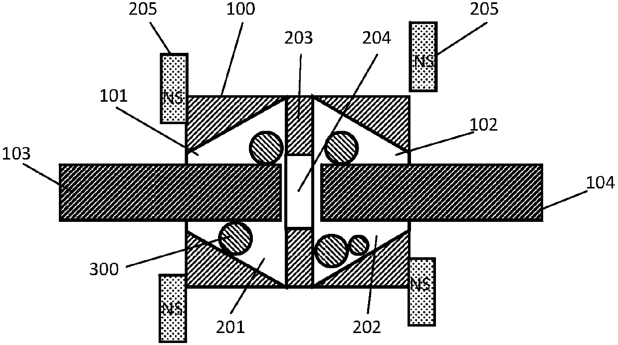
[0054] Such as figure 1 , figure 2 Shown:

[0055] The controllable stopper 100 includes a first channel 201 and a second channel 202; a moving contact body 300 is arranged in the first channel 201 and the second channel 202; Narrows, forming wide and narrow mouths;

[0056] The controllable stopper 100 also includes a docking plate 203; a docking hole 204 is provided on the docking plate 203; the docking hole 204 communicates with the first channel 201 and the second channel 202;

[0057] The controllable stopper 100 also includes a magnetic driving mechanism 205 ; under the magnetic field generated by the magnetic driving mechanism 205 , the moving contact body 300 can be driven to the narrow opening for the locking.

[0058] The wide mouth is closer to the docking hole 204 than the narrow mouth.

[0059] Both the first conductor 103 and the second conductor 104 are wires.

[0060] Specifically, the moving contact body 300 may be a sphere, an ellipsoid or a polyhedron...

no. 2 example

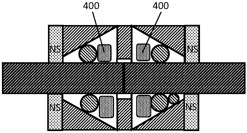
[0062] The second embodiment is a preferred example of the first embodiment. Such as image 3 Shown:

[0063] Both the first channel 201 and the second channel 202 are provided with a movement stopper 400;

[0064] Under the magnetic field generated by the magnetic driving mechanism 205, the moving stopper 400 is driven, and the moving contact body 300 is pushed to the narrow opening by the moving stopper 400 to perform the locking.

[0065] Specifically, the moving stopper 400 is a magnet capable of being affected by a magnetic field, and the moving contact body 300 is a non-magnetic body not affected by a magnetic field, such as a ceramic body or copper. In both the first passage 201 and the second passage 202 , the movement blocking body 400 is closer to the wide opening than the movement contact body 300 . The moving stop 400 is located outside the moving contact body 300 , or the moving stop 400 is embedded in the moving contact body 300 .

no. 3 example

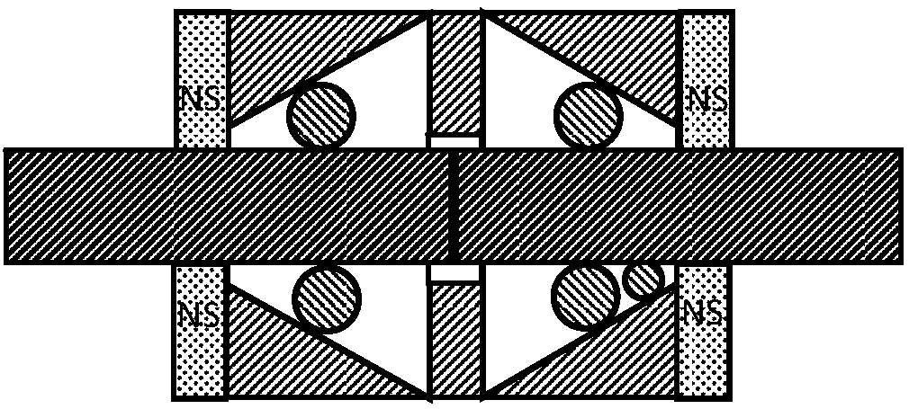
[0067] The third embodiment is a modified example of the first embodiment. Such as Figure 4 , Figure 5 Shown:

[0068] The narrow mouth is closer to the docking hole 204 than the wide mouth; or, the wide mouth is closer to the docking hole 204 than the narrow mouth;

[0069] The moving contact body 300 is a direction-abnormal body, and the moving contact body 300 in the first channel 201 and the second channel 202 can both rotate to perform the locking.

[0070] Orientation heteromorphs have different scales in different directions, such as ellipsoids.


PUM


Abstract

The invention provides a conductor contact connector. A controllable stopper (100) is provided with a first conductor connecting-inserting hole (101) and a second conductor connecting-inserting hole (102), wherein the first conductor connecting-inserting hole (101) and the second conductor connecting-inserting hole (102) are communicated with the exterior and the inner cavity of the controllable stopper (100) respectively; and the controllable stopper (100) can perform locking or releasing on a first conductor (103) inserted in the first conductor connecting-inserting hole (101) and / or a second conductor (104) inserted in the second conductor connecting-inserting hole (102). By virtue of the conductor contact connector, the connection between the wires can be quickly realized, and the connection state can be flexibly switched into a separation state. In the connection state of the wires, the electric passage where the wire is located is stable and reliable in contact, so that the effect of the wire is enhanced.

Description

technical field [0001] The present invention relates to conductor connection technology, in particular, to a conductor contact connector. Background technique [0002] In the prior art, if two wires are to be connected, it usually needs to be connected by soldering and thermal welding. Or it is often connected by means of screw tightening. However, the way of soldering and heat welding is relatively complicated, and it is not convenient for flexible connection and separation between the guides, and the way of screw tightening has the problem that the screws are easy to loosen. This leads to low reliability of electrical connection and contact in the traditional wiring mode. Contents of the invention [0003] In view of the defects in the prior art, the object of the present invention is to provide a conductor contact connector. [0004] A conductor contact connector provided according to the present invention includes: a controllable stopper 100; [0005] The controlla...

Claims


Application Information

Patent Timeline
Patent Type & Authority Applications(China)
IPC IPC(8): H01R11/01H01R11/03H01R13/506H01R13/15
CPCH01R11/01H01R11/03H01R13/15H01R13/506
Inventor 杨斌堂
Owner 杨斌堂
Why Eureka
Try Eureka