Supercharge Your Innovation With Domain-Expert AI Agents!

Disinfection device and disinfection cabinet employing same

A disinfection device and cabinet technology, which is applied in the field of disinfection cabinets and disinfection devices, can solve the problems of uneven distribution of ultraviolet rays, limited disinfection range, and inability to effectively use the space of disinfection cabinets, so as to achieve the effect of improving disinfection effect and good disinfection effect

Pending Publication Date: 2019-04-09
NINGBO FOTILE KITCHEN WARE CO LTD
View PDF1 Cites 0 Cited by
  • Summary
  • Abstract
  • Description
  • Claims
  • Application Information

AI Technical Summary

Problems solved by technology

The disinfection cabinet with the above structure makes the utensils to be sterilized close to the ultraviolet rays and achieves the disinfection effect by rotating the bowl rack. However, this cannot fundamentally solve the problem, because the position of the ultraviolet lamp tube is fixed, and the disinfection range it can cover is limited. Moreover, due to the uneven distribution of ultraviolet rays in the disinfection range, the disinfection effect of each position is also different. Turning the bowl rack can only make the utensils on the bowl racks sterilize after entering the disinfection range, but the utensils in the corners of the disinfection cabinet still cannot achieve the disinfection effect. , not only seriously affected the disinfection effect, but also caused the space in the disinfection cabinet to not be effectively utilized, making it inconvenient to use

Method used


Image

  • Disinfection device and disinfection cabinet employing same
  • Disinfection device and disinfection cabinet employing same
  • Disinfection device and disinfection cabinet employing same

Examples


Embodiment Construction

[0031] The present invention will be further described in detail below in conjunction with the accompanying drawings and embodiments.

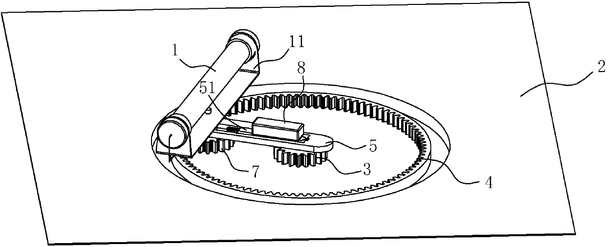
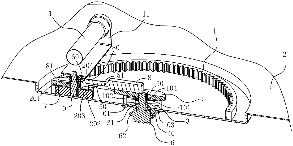
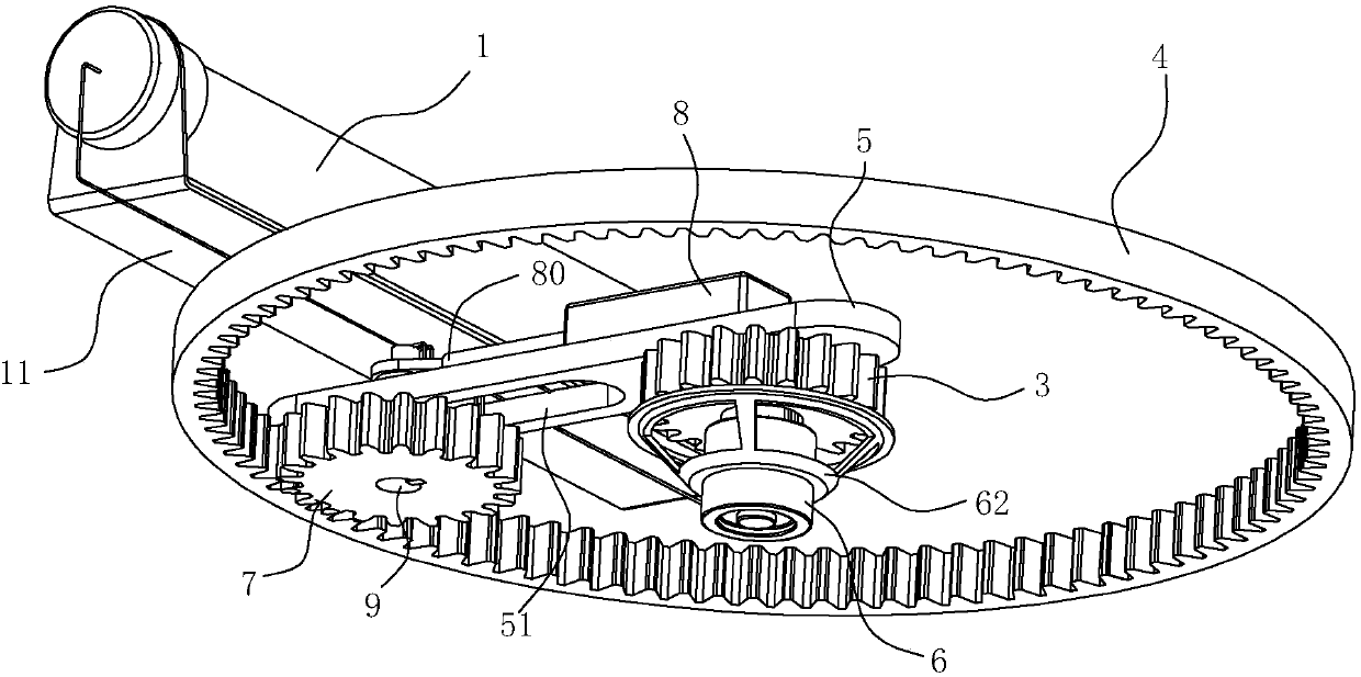
[0032] Such as Figure 1~5 As shown, the disinfection device of this embodiment includes an ultraviolet lamp 1 , a panel 2 , a first gear 3 , a ring gear 4 , a connecting rod 5 , a first driving member 6 , a second gear 7 and a second driving member 8 .

[0033] Wherein, the first gear 3 is fixed on the first side of the panel 2 , the ring gear 4 is fixed on the first side of the panel 2 , and the ring gear 4 is arranged on the outer periphery of the first gear 3 and arranged concentrically with the first gear 3 . The first end of the connecting rod 5 is rotatably arranged on the first gear 3, the second end of the connecting rod 5 is a free rotating end, and the first driving member 6 in this embodiment is arranged on the second The motor on the two sides, the output shaft 61 of the motor passes through the shaft hole 31 of the first gear 3 ...


PUM


Abstract

The invention relates to a disinfection device and a disinfection cabinet employing the disinfection device. The disinfection device comprises an ultrasonic lamp tube, a surface plate, a first gear, agear ring, a connecting rod, a first driving part, a second gear and a second driving part. As the ultrasonic lamp tube is rotationally arranged on the surface plate, when being operated, the ultrasonic lamp tube can be driven by the connecting rod to revolute around the first end of the connecting rod, meanwhile, the ultrasonic lamp tube is rotated along with the second gear, in addition, when the second gear is driven by the second driving part to be meshed with the gear ring and the first gear respectively, the ultrasonic lamp tube is in different revolution diameter ranges and rotation directions, then the rotation directions and the revolution ranges of the ultrasonic lamp tube can be changed on the basis that the rotation direction of a motor is not changed, ultraviolet rays are uniformly distributed in the disinfection cabinet, and a good disinfection effect can be achieved for components to be disinfected in different positions; by adopting the disinfection device provided bythe invention, controllable adjustment on a double-ultraviolet lamp tube disinfection range and ultraviolet ray uniformity can be achieved, and the disinfection effect can be improved.

Description

technical field [0001] The invention relates to a disinfection device and a disinfection cabinet using the disinfection device. Background technique [0002] Most of the disinfection cabinets currently on the market are high temperature or ozone disinfection. Occasionally, ultraviolet disinfection cabinets are combined with high temperature or ozone, and there are few independent ultraviolet disinfection cabinets. The reason is that the disinfection range of ultraviolet light disinfection in the cabinet is limited. It is easy to cause incomplete disinfection and has certain defects. [0003] In order to solve the above problems, the Chinese invention patent application "rotary ultraviolet disinfection cabinet" (application number: CN201010512726.5) with the application publication number CN102451478A discloses a structure, which includes a disinfection room, an electric control room, a motor, and a rectifier. A dish rack assembly and an ultraviolet disinfection lamp tube ar...

Claims


Application Information

Patent Timeline
Patent Type & Authority Applications(China)
IPC IPC(8): A61L2/10A61L2/26
CPCA61L2/10A61L2/26
Inventor 张文龙王军元刘小祥陈龙灿茅忠群诸永定
Owner NINGBO FOTILE KITCHEN WARE CO LTD
Features
  • R&D
  • Intellectual Property
  • Life Sciences
  • Materials
  • Tech Scout
  • Unparalleled Data Quality
  • Higher Quality Content
  • 60% Fewer Hallucinations
Learn More