
Self-rotation workpiece shaft positioning and clutch mechanism used in intelligent plane fine grinding machine

A technology of clutch mechanism and positioning mechanism, which is applied in the direction of machine tools suitable for grinding workpiece planes, grinding workpiece supports, and grinding machine parts, etc., which can solve the problem of single structure, inability to meet production needs, and difficulty in realizing workpiece platform positioning and other problems, to achieve the effect of convenient pick and place and improve production efficiency

Inactive Publication Date: 2019-04-09
湖南晶日智能设备科技有限公司
View PDF0 Cites 6 Cited by
  • Summary
  • Abstract
  • Description
  • Claims
  • Application Information

AI Technical Summary

Problems solved by technology

[0002] When processing glass products (such as protective glass for windows), the glass surface needs to be polished. Traditional glass grinding is done manually. The grinding strength and grinding methods of manual grinding vary from person to person. The polished surface is relatively rough, which cannot meet the needs of production.
The existing surface grinding for glass products uses ordinary grinding machines. During operation, the glass to be polished is manually placed on the processing platform, and the grinding disc is lowered to the glass surface for direct cutting. The disadvantage is that the workpiece in the existing grinding machine The platform has a single structure and does not have a clutch function, so it is difficult to realize the positioning of the workpiece platform during operation

Method used


Image

  • Self-rotation workpiece shaft positioning and clutch mechanism used in intelligent plane fine grinding machine
  • Self-rotation workpiece shaft positioning and clutch mechanism used in intelligent plane fine grinding machine
  • Self-rotation workpiece shaft positioning and clutch mechanism used in intelligent plane fine grinding machine

Examples


Embodiment Construction

[0021] In order to enable those skilled in the art to better understand the technical solution of the present invention, the present invention will be described in detail below in conjunction with the accompanying drawings. The description in this part is only exemplary and explanatory, and should not have any limiting effect on the protection scope of the present invention. .

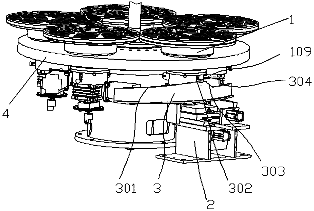
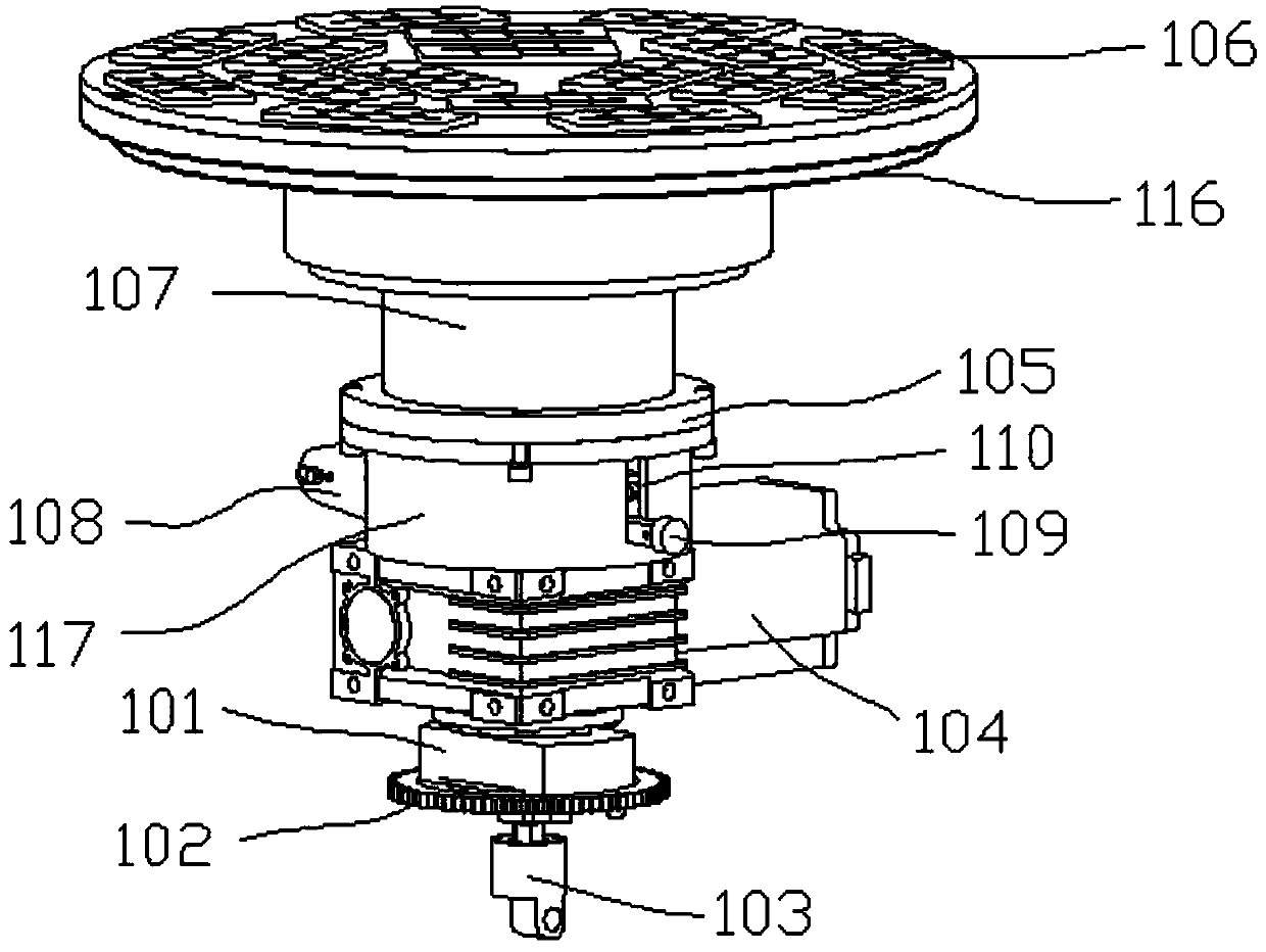
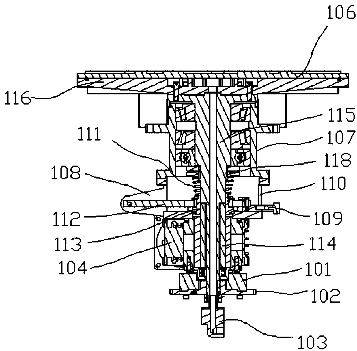
[0022] Such as Figure 1-Figure 6 As shown, the specific structure of the present invention is: it comprises autorotation workpiece shaft 1, positioning mechanism 2, clutch control plate 3 and revolution mechanism 4, and the quantity of autorotation workpiece shaft 1 is multiple and evenly distributed on revolution mechanism 4, clutch control The plate 3 is arc-shaped and arranged coaxially with the rotating shaft in the revolution mechanism 4, and the autorotation workpiece shaft 1 includes a fixed flange 116, a vacuum suction cup 106, a suction cup connecting shaft 115, a mounting flange 105, an auto...


PUM


Abstract

The invention discloses a self-rotation workpiece shaft positioning and clutch mechanism used in an intelligent plane fine grinding machine. The self-rotation workpiece shaft positioning and clutch mechanism comprises self-rotation workpiece shafts, a positioning mechanism, a clutch control panel and a revolution mechanism, the multiple self-rotation workpiece shafts are provided and are uniformlydistributed on the revolution mechanism, the clutch control panel is arc-shaped and is arranged coaxial with a rotating shaft in the revolution mechanism, self-rotation driving shafts in self-rotation workpieces are connected with suction cup connecting shafts through a mechanical clutch mechanism to realize automatic clutch, when the mechanical clutch mechanism reaches the position of the top surface in the clutch control panel, the transmission between the self-rotation driving shafts and the suction cup connecting shafts is in a disconnected state, and the top surface is arranged right above the positioning mechanism. The self-rotation workpiece shaft positioning and clutch mechanism has a mechanical clutch function, when positioning needs to be performed, the connection between self-rotation driving motors and rotating bodies is disconnected through a clutch so that positioning of a workpiece platform can be performed smoothly.

Description

technical field [0001] The invention relates to a grinding device, in particular to a clutch mechanism for positioning a rotating workpiece shaft in an intelligent plane fine grinding machine. Background technique [0002] When processing glass products (such as protective glass for windows), the glass surface needs to be polished. Traditional glass grinding is done manually. The grinding strength and grinding methods of manual grinding vary from person to person. The polished surface is relatively rough, which cannot meet the needs of production. . The existing surface grinding for glass products uses ordinary grinding machines. During operation, the glass to be polished is manually placed on the processing platform, and the grinding disc is lowered to the glass surface for direct cutting. The disadvantage is that the workpiece in the existing grinding machine The platform has a single structure and does not have a clutch function, so it is difficult to realize the positio...

Claims


Application Information

Patent Timeline
Patent Type & Authority Applications(China)
IPC IPC(8): B24B7/24B24B41/06B24B47/12B24B55/00
CPCB24B7/24B24B41/068B24B47/12B24B55/00
Inventor 张亮韩金桥
Owner 湖南晶日智能设备科技有限公司
Learn More