
Sterile spray pump

A technology of aseptic spraying and spraying nozzles, which is applied in the direction of spraying devices, closures, packaging, etc., can solve the problems of liquid medicine pollution, affecting the use effect, unstable dosage, etc., and achieve the effect of avoiding pollution

Active Publication Date: 2019-04-09
SHENZHEN BONA MEDICINAL PACKAGING MATERIAL CO LTD
View PDF5 Cites 2 Cited by
  • Summary
  • Abstract
  • Description
  • Claims
  • Application Information

AI Technical Summary

Problems solved by technology

[0003] 1. Ordinary spray pumps mostly have an open nozzle structure. After use, the air directly contacts the liquid medicine at the nozzle, and the liquid medicine remains inside the nozzle. The remaining medicinal liquid is sprayed out again during use, which directly affects the use effect
[0004] 2. Ordinary spray pumps are designed with a return air structure, which is used to replenish the external air into the container during the use of the spray pump, otherwise the spray pump cannot work normally, but the external air directly entering the container will affect the liquid medicine in the container. create pollution
[0005] 3. Most sterile spray pumps are in the form of vacuum pumps, and the volume of liquid medicine in the container installed with the vacuum pump should not exceed 2 / 3 of the container, and the container capacity is subject to certain restrictions. If the container capacity is too large, the internal negative pressure is too large, It will lead to unstable dose; at the same time, with the increase of the number of uses of the spray pump, the internal pressure of the container will continue to increase, resulting in the gradual attenuation of the spray dose of the spray pump, which will lead to the inability of all the liquid in the container to be used up.

Method used

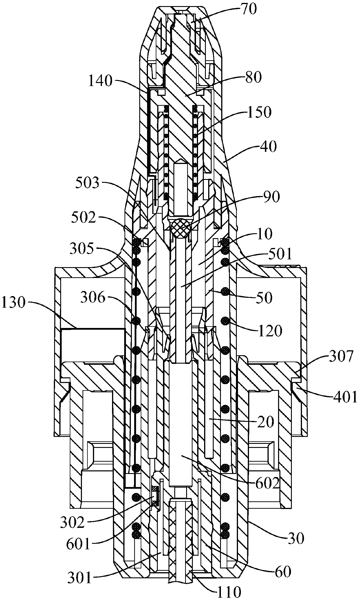
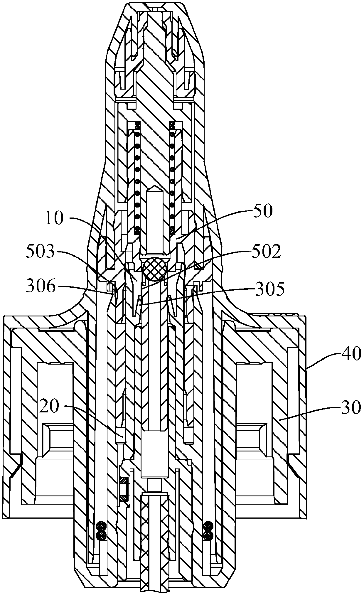
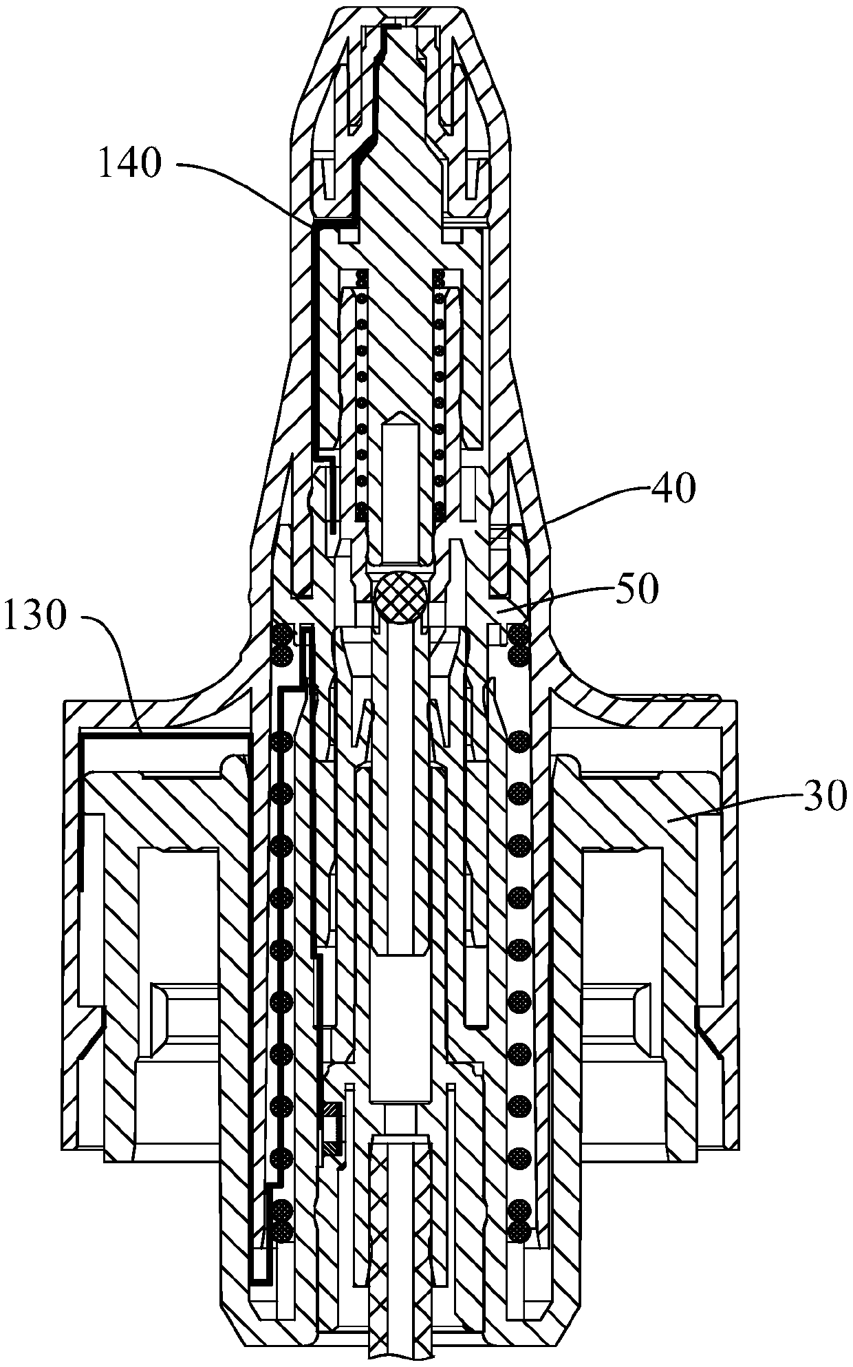

Image

  • Sterile spray pump
  • Sterile spray pump
  • Sterile spray pump

Examples


Embodiment Construction

[0093] The implementation of the present invention will be illustrated by specific specific examples below, and those skilled in the art can easily understand other advantages and effects of the present invention from the contents disclosed in this specification.

[0094] It should be noted that the structures, proportions, sizes, etc. drawn in the drawings of this specification are only used to match the content disclosed in the specification, for those who are familiar with this technology to understand and read, and are not used to limit the conditions for the implementation of the present invention. Therefore, there is no technical substantive meaning, and any modification of structure, change of proportional relationship or adjustment of size shall still fall within the scope of the disclosure of the present invention without affecting the functions and objectives of the present invention. within the scope of technical content. At the same time, terms such as "upper", "lo...


PUM


Abstract

The invention provides a sterile spray pump. The sterile spray pump comprises a main piston, a spray head and a subsidiary piston fixed inside the spray head, wherein the subsidiary piston is installed to the main piston in a manner of being capable of moving up and down, and a first compression space and a second compression space are formed between the subsidiary piston and the main piston, themain piston is internally provided with a main liquid absorption cavity communicating with the inner cavity of a container and an air replenishing mouth communicating with the main liquid absorption cavity, the air replenishing mouth communicates with the second compression space and is internally and fixedly provided with a filter element covering the air replenishing mouth, the subsidiary pistonis provided with a subsidiary liquid absorption cavity, a first air exhaust component and a second air exhaust component which communicate with the main liquid absorption cavity, the spray head is pressed downwards and after the main piston is connected with the first air exhaust component and the second air exhaust component in an abutted manner, the first compression space communicates with themain liquid absorption cavity through the first air exhaust component, and the second compression space communicates with the outer portion of the sterile spray pump through the second air exhaust component. By means of the sterile spray pump, external air can be replenished into the container normally, therefore, the sterile spray pump is not affected by the loading quantity and the number of used times.

Description

technical field [0001] The invention relates to the storage field of liquids (such as liquid medicine, liquid cosmetics, liquid cleaning agents, etc.), in particular to an aseptic spray pump for spraying liquid in a container. Background technique [0002] A spray pump is a pump that sprays a substance in a liquid state in a spray state when the user presses it. When the spray pump is used to spray liquid medicine, the spray pump usually has a sterile requirement. At present, there are various forms of spray pumps on the market, but they all have the following disadvantages: [0003] 1. Ordinary spray pumps mostly have an open nozzle structure. After use, the air directly contacts the liquid medicine at the nozzle, and the liquid medicine remains inside the nozzle. Residual liquid medicine is sprayed out again during use, directly influences use effect. [0004] 2. Ordinary spray pumps are designed with a return air structure, which is used to replenish the external air in...

Claims


Application Information

Patent Timeline
Patent Type & Authority Applications(China)
IPC IPC(8): B65D47/34
CPCB05B11/1042B05B11/1001A61M11/007A61M2205/75A61M2205/3331B05B11/1004B05B11/1074B05B11/00444B05B11/0067B05B11/0075B05B11/1047A61M11/00
Inventor 邓云化
Owner SHENZHEN BONA MEDICINAL PACKAGING MATERIAL CO LTD
Learn More