A Mechanical Tension Tubing Anchor

A tubing anchor and mechanical technology, applied in the direction of drill pipe, casing, wellbore/well parts, etc., can solve the problems of inconvenient reuse, low work efficiency, unreliable anchoring, etc., and achieve rapid reuse, simple operation, Ease of use for promotion

Active Publication Date: 2019-08-16
DAQING TIANDEZHONG PETROLEUM SCI & TECH CO LTD
View PDF1 Cites 0 Cited by
  • Summary
  • Abstract
  • Description
  • Claims
  • Application Information

AI Technical Summary

Problems solved by technology

[0006] Aiming at the deficiencies of the prior art, the present invention provides a mechanical tension tubing anchor with double-arranged sawtooth cutting edges, which can cooperate with the limit blades installed with vertical blades to prevent the anchor slips from slipping on the surface of the pipe wall. Horizontal rotation, that is, to avoid the rotation of the tubing anchor and to avoid affecting the anchoring effect of the seat seal. At the same time, the return spring is used to retract and reset the slips. After the anchoring work is completed, when the joint seat is lifted, the slips are automatically closed. , Reset, reasonable design, simple operation, easy to popularize and use, etc., solves the problem that the existing mechanical tension tubing anchor is easy to cause the overall horizontal rotation due to the effect of pressure during use, making the anchor unreliable, complicated to operate, and inconvenient to carry out Repeated use, low work efficiency

Method used


Image

  • A Mechanical Tension Tubing Anchor
  • A Mechanical Tension Tubing Anchor
  • A Mechanical Tension Tubing Anchor

Examples


Embodiment Construction

[0030] The following will clearly and completely describe the technical solutions in the embodiments of the present invention with reference to the accompanying drawings in the embodiments of the present invention. Obviously, the described embodiments are only some, not all, embodiments of the present invention. Based on the embodiments of the present invention, all other embodiments obtained by persons of ordinary skill in the art without making creative efforts belong to the protection scope of the present invention.

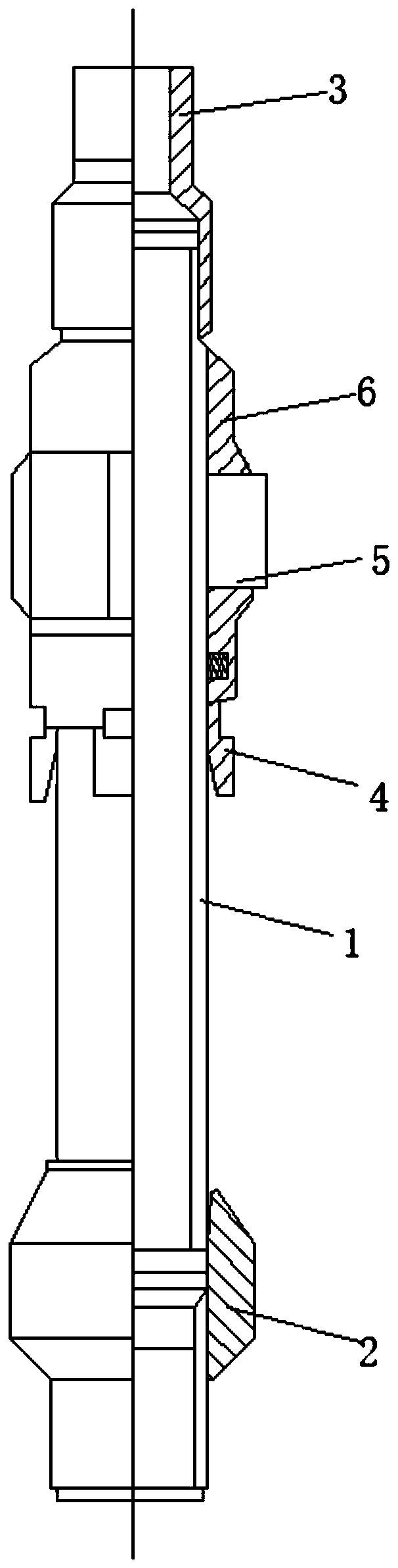
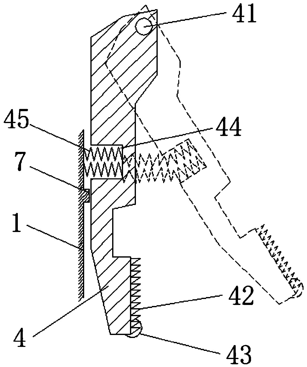
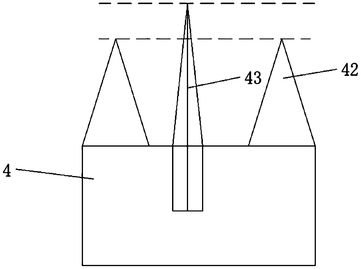
[0031] A mechanical tension tubing anchor, see figure 1 , including a central tube 1, a lower joint seat 2, an upper joint seat 3, a slip piece 4, an insertion hole 41, a serration 42, a limit blade 43, a spring groove 44, a return spring 45, a slip fixing collar 5, Placement slot 51, rotating shaft 52, centralizer structure 6 and stopper 7, the lower end of the central tube 1 is provided with a lower joint sleeve 2 that slides up and down, and the upper end o...


PUM


Abstract

The invention relates to the technical field of oil tube fixing equipment and discloses a mechanical type tension oil tube anchor. Slip sheets are distributed on the outer side of the middle part of acenter tube circumferentially; the outer end surface of each slip sheet is a plane; sawteeth are formed in the surface of the slip sheet; the sawteeth are arranged in two columns longitudinally; single column of sawteeth are arranged in a squamous staggered way; a round-sheet-shaped limiting blade is embedded at the middle position of the lower end part of the slip sheet; a spring groove is formed in the middle part of the left side surface of the slip sheet; a reset spring is embedded in the spring groove; the two ends of the reset spring are connected with the inner groove surface of the spring groove and the outer surface of the center tube. The mechanical type tension oil tube anchor is provided with double columns of sawtooth cutting edges and can cooperate with the limiting blades adopting vertical type blade mounting, so that rotation of an oil tube anchoring part is avoided and the influence on the seat sealing anchoring effect is avoided; in addition, the slip is retracted and reset by the reset spring, and the slip sheets can be folded and reset automatically after anchoring work is completed and when a joint base is lifted.

Description

technical field [0001] The invention relates to the technical field of oil pipe fixing equipment, in particular to a mechanical tension oil pipe anchor. Background technique [0002] In the process of downhole measure operations and rod pumping production, due to the influence of some factors (continuous drop of dynamic liquid level, deeper and deeper pump hanging, hot washing measures, etc.), the production or measure string will inevitably face There are some problems such as expansion and contraction of the pipe string and deterioration of the stress state. At present, the downhole tubing anchor (hereinafter referred to as tubing anchor) is mainly used to solve the above problems on site. [0003] The tubing anchor is a downhole device for anchoring downhole tubing strings in production and measure wells. It can improve the stress state of the tubing string, reduce the fatigue damage of the tubing string, control the expansion and contraction of the tubing string, reduce...

Claims


Application Information

Patent Timeline
Patent Type & Authority Patents(China)
IPC IPC(8): E21B23/00E21B19/10
CPCE21B19/10E21B23/00
Inventor 张淞源张虎
Owner DAQING TIANDEZHONG PETROLEUM SCI & TECH CO LTD
Why Eureka
Try Eureka