
Orthopedic device and method for lower limb elevation and stabilization

a technology of orthopedic devices and stabilizers, which is applied in the direction of restraining devices, applications, transportation and packaging, etc., can solve the problems of unwanted and potentially dangerous torsion or torque to the knee joint of the patient recovering from knee surgery, the patient may incur serious pain, and the knee may be reinjured, so as to maintain the extension of the knee joint and unwanted torsion, and promote proper healing

Active Publication Date: 2021-10-26
BONE FOAM
View PDF46 Cites 2 Cited by
  • Summary
  • Abstract
  • Description
  • Claims
  • Application Information

AI Technical Summary

Benefits of technology

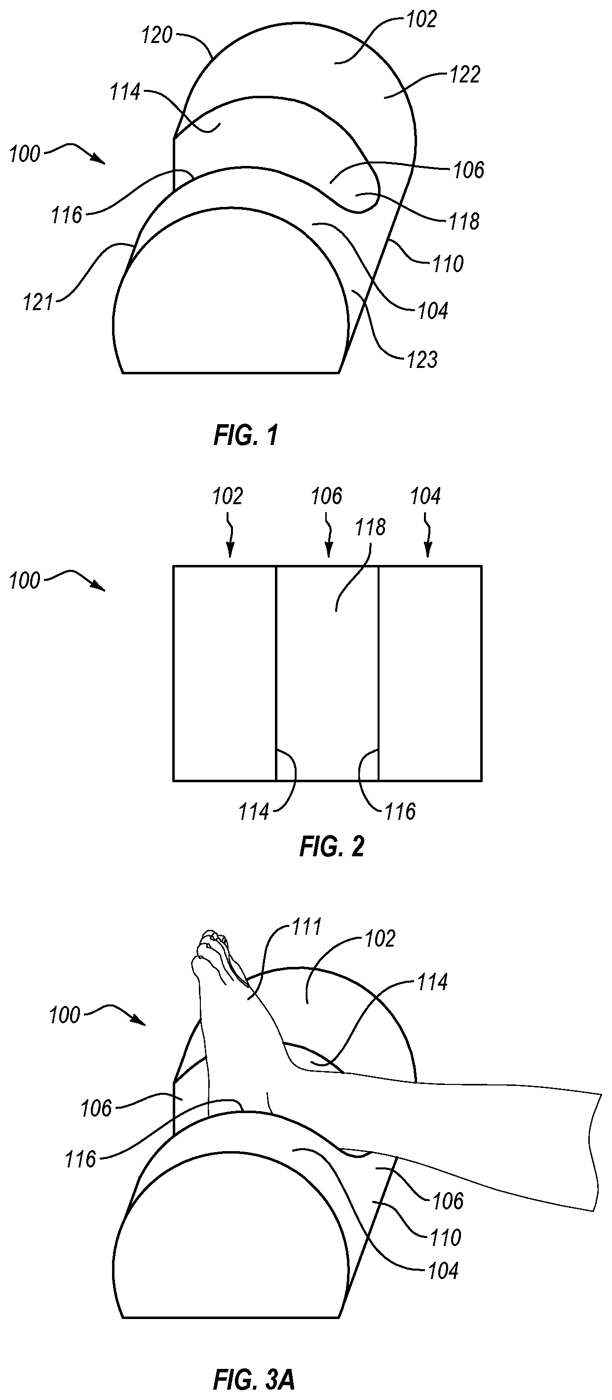
[0008]Disclosed herein are orthopedic devices configured for supporting and restraining rotation of the foot of a patient who is recovering from surgery, such as knee surgery. The devices help maintain knee extension and unwanted torsion on the knee joint by restraining foot rotation. Continuous extension and of a surgically repaired knee and protection against unwanted torsion of the knee following surgery promote proper healing.
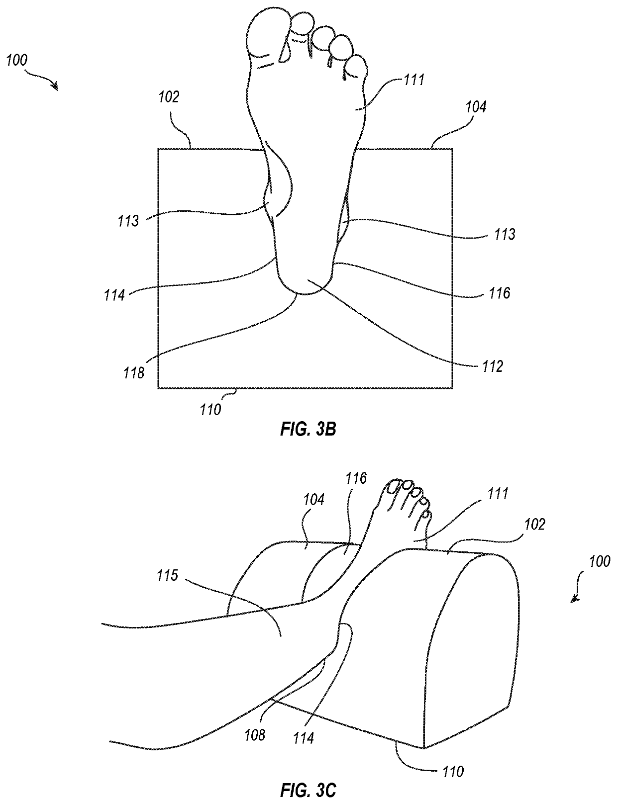
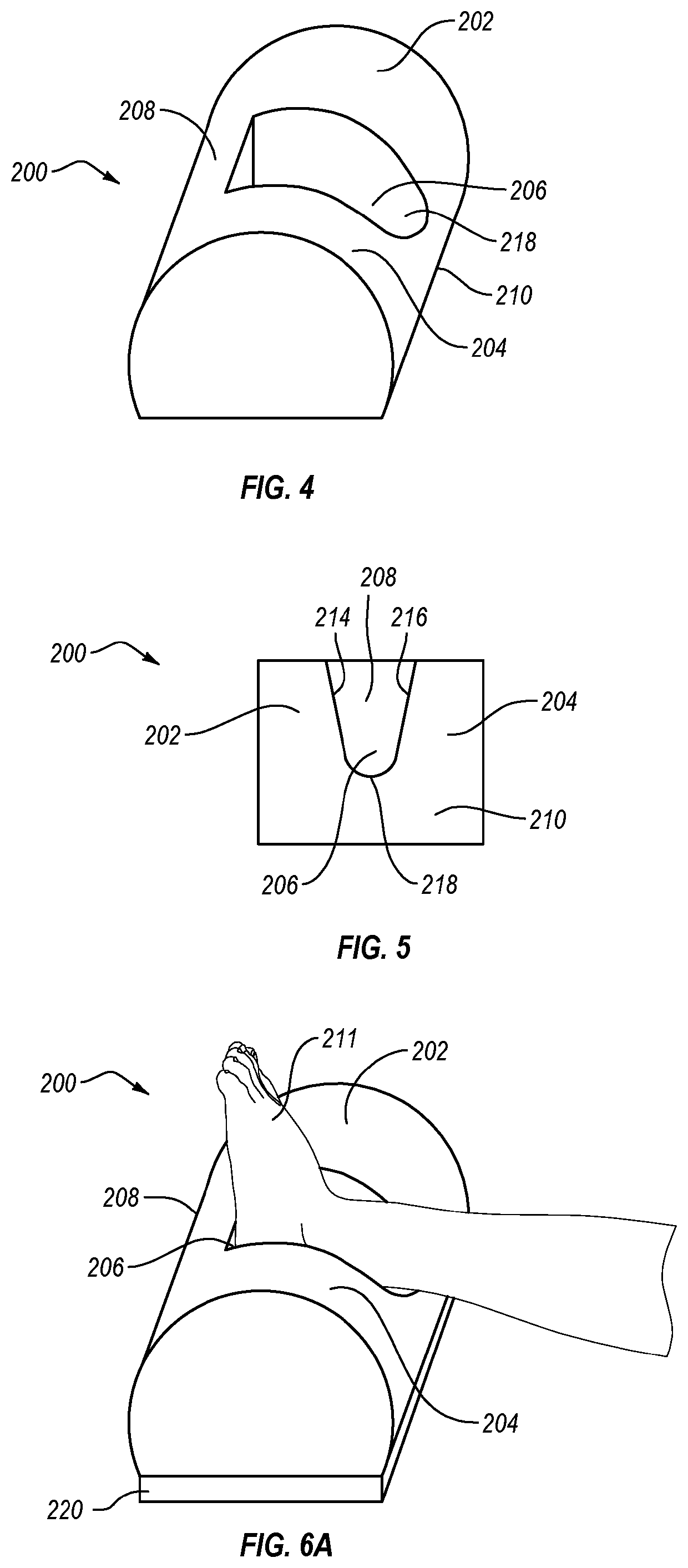
[0010]Devices disclosed herein are configured to limit unwanted motion of the foot to stabilize and protect the recovering knee. For example, when the patient is lying in a supine position, the foot tends to rotate outwardly (laterally) or inwardly (medially) due to relaxation or gravity, which may, in turn, cause the tibia and fibula to rotate laterally or medially relative to the femur. This rotation may cause unwanted and potentially dangerous torsion or torque to a recovering knee joint. For example, a patient recovering from knee surgery may incur serious pain, reinjure the knee, and / or even require additional surgery if the knee is not properly protected from such torsion. The disclosed devices are configured to cradle and support the foot, including the ankle and heel, in a manner that prevents such rotations and allows the knee to be free of torsional moments.
[0011]Support devices as disclosed herein may be used to isolate, elevate, immobilize, and support an ankle to provide restraint against foot and lower leg rotation. The patient may lie, for example, in a supine position, with the foot, including ankle and heel, resting on or in a cavity of continuous or varying depth formed in the support device. The support device may include a main body with a generally flat lower surface, which can be sufficiently wide to prevent or limit unwanted rotation of the support device in response to foot rotations. The support device includes two spaced-apart lateral ridges extending upwardly along or near lateral edges of the main body, and a medial depression between the lateral ridges that provides a support surface and cavity of continuous or varying depth on and in which the foot and ankle may be positioned. The lateral ridges can be sufficiently tall relative to the foot to restrain the foot from medial and lateral rotations. The lateral ridges can be spaced apart to permit a foot to be placed into or lifted out of the medial depression without having to manipulate the support device (e.g., without having to spread the lateral ridges apart when inserting a foot into or removing the foot from the medial cavity). This ease of insertion and removal helps prevent injury to the patient's knee.
[0012]The support device may further comprise a medial ridge connected to and extending transversely between the lateral ridges to limit plantar flexion of the foot during recovery. The support device can terminate at a location proximal to the ankle and distal to the calf muscle so that the calf muscle and region behind the knee are not in contact with the support device and, in some embodiments, are not in contact with surface on which the patient lies. This assists in maintaining the knee in an extended position.

Problems solved by technology

This rotation may cause unwanted and potentially dangerous torsion or torque to a recovering knee joint.
For example, a patient recovering from knee surgery may incur serious pain, reinjure the knee, and / or even require additional surgery if the knee is not properly protected from such torsion.

Method used


Image

  • Orthopedic device and method for lower limb elevation and stabilization
  • Orthopedic device and method for lower limb elevation and stabilization
  • Orthopedic device and method for lower limb elevation and stabilization

Examples


Embodiment Construction

[0024]Disclosed herein are orthopedic devices configured for supporting and restraining rotation of the foot of a patient who is recovering from surgery, such as knee surgery. The devices help maintain knee extension and unwanted torsion on the knee joint by restraining foot rotation. Continuous extension and of a surgically repaired knee and protection against unwanted torsion of the knee following surgery promote proper healing. Some embodiments are designed to also limit plantar flexion of the foot.

[0025]For lower limb medical recovery, such as following knee surgery or injury, a patient often lies or is placed in a supine position, i.e. with the front (anterior) portion of the lower limb facing up and the back portion of the lower limb (posterior) facing down. As part of the recovery, it is often required for the lower limb to remain in a certain or fixed position, being isolated and elevated, for a period of time. Also, elevating the lower leg from the bed surface may be desira...


PUM


Abstract

A support device provides elevation and support for a patient's foot, including ankle and heal, and limits lateral and medial rotation of the foot. This protects the knee from injury while healing. The device includes a generally flat main body, two spaced-apart lateral ridges, and a medial depression between the lateral ridges that provides a support surface on which the foot may be positioned. The lateral ridges can extend to a height above the support surface so that inner side surfaces of the lateral ridges are adjacent to a majority of a foot placed in the medial depression. The lateral ridges can terminate below a top of the foot to permit unrestricted ventilation and access to the foot. The lateral ridges can be spaced apart to facilitate placement of a foot onto and removal of the foot from the support surface without manual manipulation of the device.

Description

CROSS REFERENCE TO RELATED APPLICATION[0001]This Application is a continuation-in-part of U.S. patent application Ser. No. 15 / 676,643, filed Aug. 14, 2017, which is a continuation-in-part of U.S. patent application Ser. No. 14 / 709,630, filed May 12, 2015, abandoned, the disclosures of which are incorporated herein by reference in their entirety.BACKGROUND[0002]Following injury or a lower limb surgical procedure, especially knee surgery (such as total knee replacement, arthroscopic knee surgery, or ACL surgery), a patient often lies or is placed in a supine position, i.e. with the front (anterior) portion of the lower limb facing up and the back portion of the lower limb (posterior) facing downward. As part of the recovery, it is often required that the lower limb remain in a certain position, being isolated, immobilized, and elevated, for a prescribed time period.[0003]Many kinds of undesirable movements are possible, however, during this time period of recovery. For example, natura...

Claims


Application Information

Patent Timeline
Patent Type & Authority Patents(United States)
IPC IPC(8): A61G7/05A61G13/12A61G13/10A61G7/057A61F5/37A61G7/075
CPCA61G13/125A61F5/37A61F5/3769A61G7/05723A61G7/0755A61G13/10A61G2200/56A61G2210/50
Inventor LUCEY, STEPHEN DAVISROBRAN, CHAD L.
Owner BONE FOAM
Learn More