
A surface contact positioning pin and its manufacturing jig

A positioning pin and surface contact technology, applied in the direction of manufacturing tools, positioning devices, clamping, etc., can solve problems such as difficult processes and long contact time with positioning pins, reduce production costs, increase contact area, and prevent product displacement Effect

Active Publication Date: 2016-08-24
金牌模具(常熟)有限公司
View PDF8 Cites 0 Cited by
  • Summary
  • Abstract
  • Description
  • Claims
  • Application Information

AI Technical Summary

Problems solved by technology

[0004] In view of the shortcomings of the prior art described above, the purpose of the present invention is to provide a surface contact positioning pin and its manufacturing fixture, which can make positioning more reliable, high precision, and convenient adjustment; another purpose of the present invention The aim is to provide a tool for manufacturing the locating pin, which can accurately and quickly clamp the locating pin to be processed, and solve the problems of long time and difficult process for processing the surface contacting the locating pin

Method used


Image

  • A surface contact positioning pin and its manufacturing jig
  • A surface contact positioning pin and its manufacturing jig
  • A surface contact positioning pin and its manufacturing jig

Examples


Embodiment Construction

[0033] The implementation of the present invention will be illustrated by specific specific examples below, and those skilled in the art can easily understand other advantages and effects of the present invention from the contents disclosed in this specification.

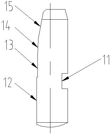
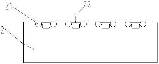
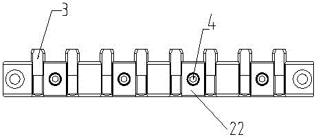
[0034] see figure 1 and Figure 16 . It should be noted that the structures, proportions, sizes, etc. shown in the drawings attached to this specification are only used to match the content disclosed in the specification, for those who are familiar with this technology to understand and read, and are not used to limit the implementation of the present invention. Limiting conditions, so there is no technical substantive meaning, any modification of structure, change of proportional relationship or adjustment of size, without affecting the effect and purpose of the present invention, should still fall within the scope of the present invention. The disclosed technical content must be within the scope covered. At the...


PUM


Abstract

The invention provides a surface contact positioning pin and a manufacturing clamp thereof. A fixing groove is formed in one side surface of the surface contact positioning pin; an anti-rotation surface, a working surface, a second guide surface and a first guide surface are arranged on the other side of a positioning pin body from head to tail. A common standard round positioning pin is changed to be in a specific shape required for shape positioning of a product in a die, and the fixing groove is formed and can be matched with a bulge in the stamping die, so that a conventional line contact positioning pin can be changed to a surface contact positioning pin, the contact area of the positioning pin and the positioning part of the product can be enlarged, the product can be better positioned and fixed and is prevented from shifting, and the positioning pin is prevented from transversely rotating or axially moving in the die. The manufacturing clamp for manufacturing a positioning die is specially used for the surface contact positioning pin, the positioning pin can be better clamped, the required surface can be conveniently cut, the pertinence is strong, the processing time is greatly shortened, and the production cost is reduced.

Description

technical field [0001] The invention relates to a novel positioning pin and a fixture for manufacturing the positioning pin. Background technique [0002] In the prior art, positioning pins are widely used in mechanical assembly processes for positioning between parts and preventing relative displacement between parts. Since the standard locating pins in the prior art all have a unified general cylindrical shape, which is suitable for the positioning of round holes, if they cooperate with the planes of other components, it is difficult to completely contact and fit them. Especially for the precise positioning of the product shape in the stamping die, it is difficult for the traditional cylindrical positioning pin to completely fit the surface, resulting in unreliable positioning and low precision. As the domestic and foreign economic situation continues to change, it has had a huge impact on the manufacturing industry. How to effectively reduce manufacturing costs, increase...

Claims


Application Information

Patent Timeline
Patent Type & Authority Patents(China)
IPC IPC(8): F16B19/02B23Q3/00B24B41/06
CPCB23Q3/00B24B41/06F16B19/02
Inventor 沈冰徐进
Owner 金牌模具(常熟)有限公司
Learn More