
Sand layer three-dimensional grouting test device capable of simulating actual working conditions, and test method thereof

A technology of actual working conditions and grouting tests, applied in the field of geotechnical engineering, can solve the problems of inability to simulate grouting conditions, complexity, difficulty in accurately obtaining reasonable grouting pressure and grout ratio, etc.

Inactive Publication Date: 2019-04-09
SUN YAT SEN UNIV
View PDF7 Cites 23 Cited by
  • Summary
  • Abstract
  • Description
  • Claims
  • Application Information

AI Technical Summary

Problems solved by technology

However, due to the complexity of the grouting process, there are many deficiencies in the existing grouting test device
For example: 1. The actual grouting is to inject grout into the formation at a certain depth. The grouting hole and the surrounding rock and soil are affected by the grouting conditions such as complex ground stress conditions and pore water pressure. The existing grouting test device is basically It is impossible to simulate the actual grouting conditions. In addition, the existing grouting test device cannot evaluate the mechanical properties of the grouting body formed after the grout spreads and solidifies. Therefore, it is difficult to carry out the simulation test through the existing grouting test device Obtain reasonable grouting pressure and grout ratio under different working conditions and sand layer characteristics
2. The actual grouting is to uniformly reinforce the surrounding soil. It is also necessary to use radial grouting to carry out radial grouting on the soil around the grouting pipe, and consider the reasonable grouting pressure and grout mix of radial grouting. Ratio and other parameters, and check the grouting effect, but the existing grouting test device can only perform axial grouting, so it is impossible to simulate and study the radial grouting process

Method used


Image

  • Sand layer three-dimensional grouting test device capable of simulating actual working conditions, and test method thereof
  • Sand layer three-dimensional grouting test device capable of simulating actual working conditions, and test method thereof
  • Sand layer three-dimensional grouting test device capable of simulating actual working conditions, and test method thereof

Examples


Embodiment Construction

[0028] The technical solutions in the embodiments of the present invention will be clearly and completely described below in conjunction with the accompanying drawings. Apparently, the described embodiments are only part of the embodiments of the present invention, not all of them. Based on the embodiments of the present invention, all other embodiments obtained by persons of ordinary skill in the art without creative efforts fall within the protection scope of the present invention.

[0029] It should be noted that if the embodiment of the present invention involves directional indications (such as up, down, left, right, front, back, top, bottom, inside, outside, vertical, horizontal, vertical, counterclockwise, clockwise, circumferential direction, radial direction, axial direction...), the directional indication is only used to explain the relative positional relationship, movement conditions, etc. When a change occurs, the directional indication changes accordingly.

[00...


PUM


Abstract

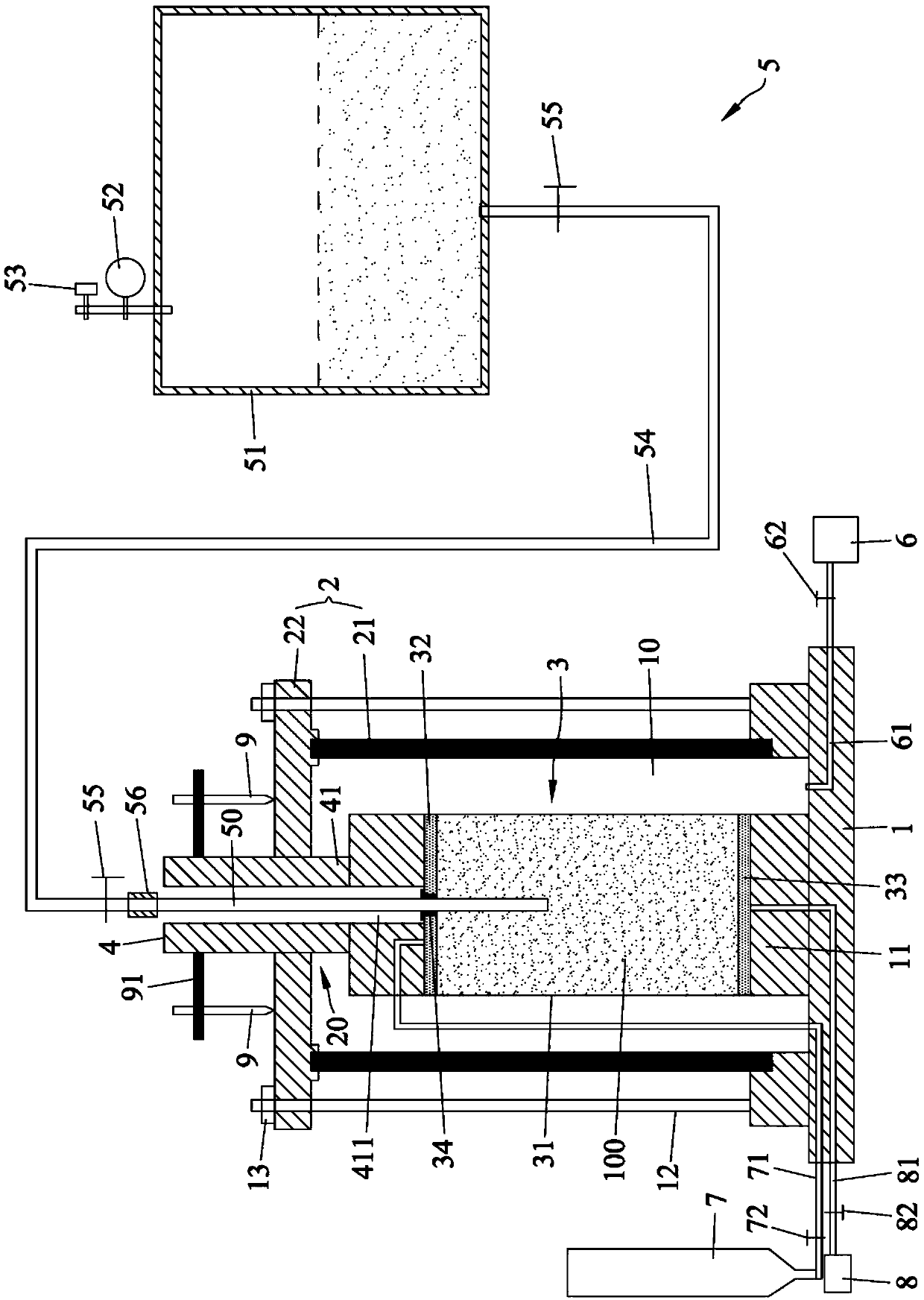
The invention discloses a sand layer three-dimensional grouting test device capable of simulating actual working conditions, and a test method thereof. Different crustal stress conditions and different pore water pressures can be simulated according to actual grouting requirements, meanwhile soil samples with different proportions can be made according to test demands to simulate different sand layer characteristics, after grouting, the volume change amount and the axial displacement change of the soil sample in a rubber film can be observed by a volume strain measuring device and an axial displacement measuring device, images obtained before and after the grouting are compared to obtain a deformation value of the middle of the rubber film, and then reasonable grouting pressure and slurryratios under different working conditions and sand layer characteristics are researched according to the obtained volume change amount and the axial displacement change of the soil sample, and the deformation value of the middle of the rubber film, and the mechanical properties of a grouting body are also detected. In addition, a grouting tube of the test device can be changed according to the engineering and experimental needs, the simulation and research of a radial grouting process are achieved, and the mechanical effect of radial grouting is tested.

Description

technical field [0001] The invention relates to the technical field of geotechnical engineering, in particular to a sand layer three-dimensional grouting test device capable of simulating actual working conditions and a test method thereof. Background technique [0002] With the development of urbanization, the development and utilization of underground space is constantly accelerating, and more underground buildings such as subway tunnels, municipal tunnels, and pipeline common trenches need to be planned and built. During the construction of underground buildings, especially tunnel projects, when water-rich sand layers are encountered, water and sand inrush often occur, causing instability and endangering the safety of engineering construction and the safety of ground facilities. In order to solve the above problems, the current mainstream treatment method is to make a slurry of specific materials according to a certain ratio according to the needs of the project, and inje...

Claims


Application Information

Patent Timeline
Patent Type & Authority Applications(China)
IPC IPC(8): G01N33/24
CPCG01N33/24
Inventor 马建军梁禹黄林冲
Owner SUN YAT SEN UNIV
Learn More