Coupling Z axis rotating device

A rotating device and Z-axis technology, which is applied in auxiliary devices, auxiliary welding equipment, welding/cutting auxiliary equipment, etc., can solve the problem of light-seeking deflection angle accuracy, full runout of the end face of optical devices and coaxiality that cannot meet the requirements of coupling light-seeking and welding Requirements and other issues to achieve the effect of improving efficiency

Active Publication Date: 2019-04-12
GUANGXUN SCI & TECH WUHAN
View PDF9 Cites 0 Cited by
  • Summary
  • Abstract
  • Description
  • Claims
  • Application Information

AI Technical Summary

Problems solved by technology

[0004] The invention provides a coupling Z-axis rotation device. The technical problem to be solved by the invention is to solve the problem that the accuracy of the deflection angle of the light-seeking deflection of the existing coaxial optical device when rotating and the full runout of the end face of the optical device and the coaxiality cannot meet the requirements of the coupling and seeking. Technical issues with light and soldering requirements

Method used


Image

  • Coupling Z axis rotating device
  • Coupling Z axis rotating device
  • Coupling Z axis rotating device

Examples


Embodiment 1

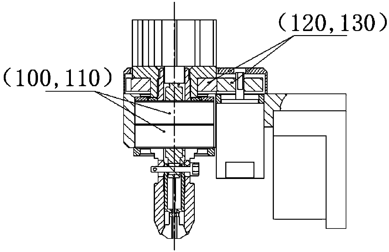
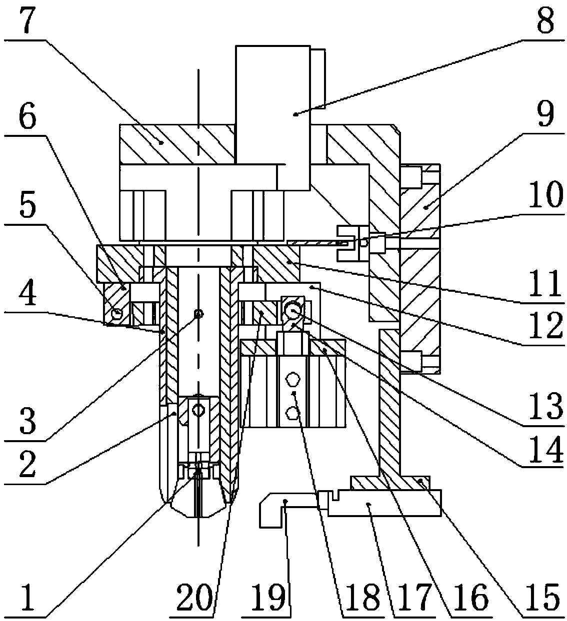
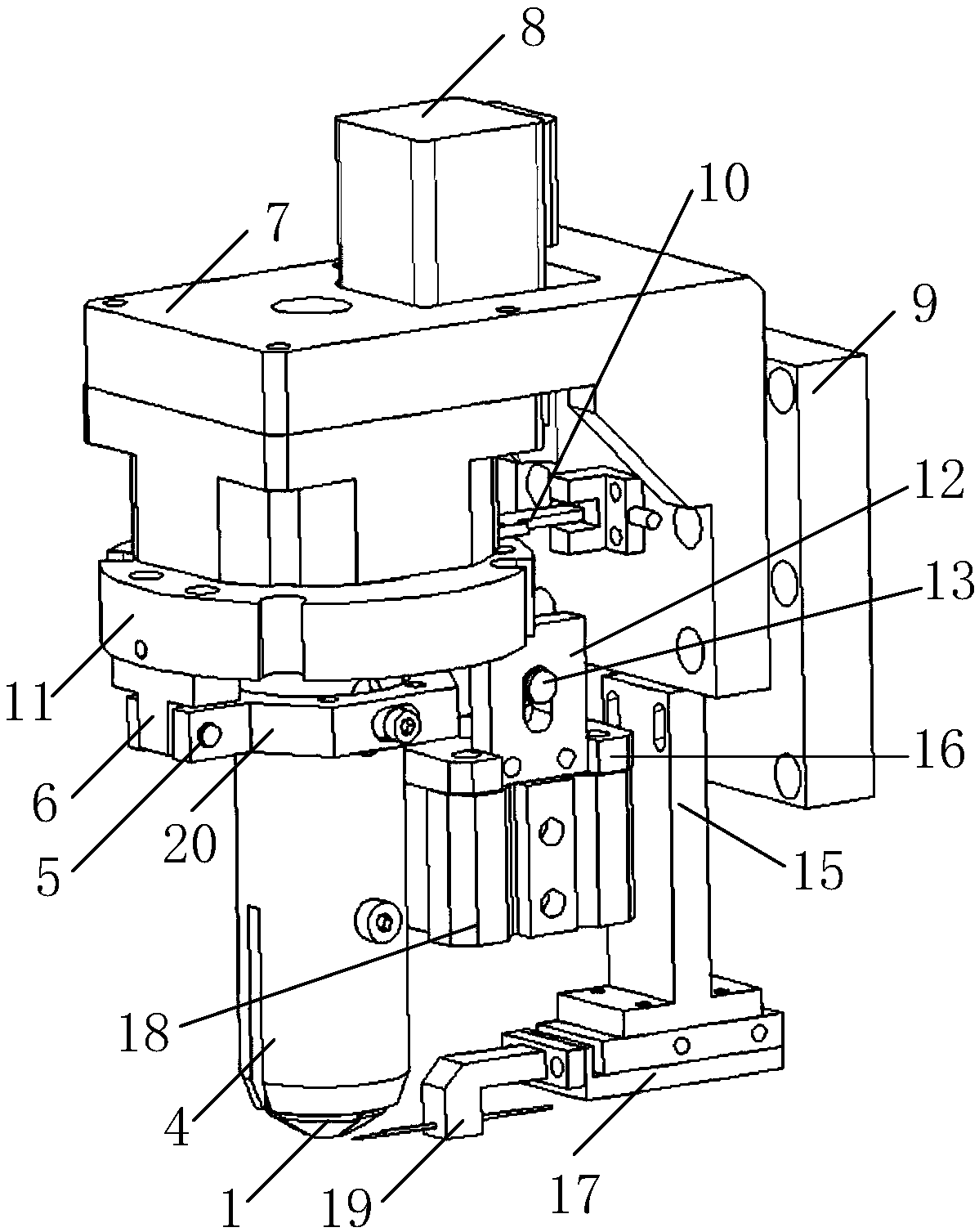
[0045] Embodiment 1 of the present invention provides a coupling Z-axis rotation device, such as Figure 2 to Figure 8 As shown, it includes a rotating part, a locking part, and a clamping part; the clamping part is arranged on the rotating part, and the locking part is arranged on the rotating part; the rotating part is used to rotate the The locking part and the clamping part; the clamping part is used to clamp the optical device, and the clamping part includes an upper locking mouth 1 and an upper chuck fixing sleeve 4, and the upper locking mouth 1 is provided with an elastic fiber The insert 1-2, the end face of the elastic fiber insert 1-2 is used to contact the end face of the optical device; the upper chuck inner sleeve 2 of the locking part is embedded in the upper chuck fixing sleeve 4 and The upper locking mouths 1 can move up and down, and the upper chuck inner sleeve 2 is used to lock the upper locking mouths 1 when going down.

[0046] The coupling Z-axis rotati...

Embodiment 2

[0051] Embodiment 2 of the present invention provides a coupling Z-axis rotation device, such as Figure 2 to Figure 8 As shown, it includes a rotating part, a locking part, and a clamping part; the clamping part is arranged on the rotating part, and the locking part is arranged on the rotating part; the rotating part is used to rotate the The locking part and the clamping part; the clamping part is used to clamp the optical device, and the clamping part includes an upper locking mouth 1 and an upper chuck fixing sleeve 4, and the upper locking mouth 1 is provided with an elastic fiber The insert 1-2, the end face of the elastic fiber insert 1-2 is used to contact the end face of the optical device; the upper chuck inner sleeve 2 of the locking part is embedded in the upper chuck fixing sleeve 4 and The upper locking mouth 1 can move up and down, and the second light hole 4-1 is used to lock the upper locking mouth 1 when the inner sleeve 2 of the upper chuck is going down.

...


PUM


Abstract

The invention discloses a coupling Z axis rotating device which adopts a rotary part to drive a locking part and a clamping part to rotate to ensure deflection angle precision when an optical device rotates; the clamping part adopts an upper locking nozzle with an elastic fibre insert to clamp the optical device; the end surface of the elastic fibre insert is in contact with the end surface of theoptical device; when an upper chuck inner sleeve of the locking part descends, the upper locking nozzle can be locked, so that the optical device further can be locked, and therefore, end surface full indicator movement and coaxiality of the optical device can be ensured to meet technical requirements of light-seeking and welding during coupling and light-seeking, and coupling and light-seeking efficiency, working efficiency and welding quality are improved.

Description

【Technical field】 [0001] The invention relates to the technical field of optical device coupling equipment, in particular to a coupling Z-axis rotation device. 【Background technique】 [0002] For the automatic coupling equipment of coaxial optical devices, when coupling three-piece coaxial optical devices, it is necessary to deflect the angle of TO and adapter to ensure the coupling power. Solder package for coupled devices. Existing automatic coupling Z-axis rotation mechanism, such as figure 1 As shown, bearings (100, 110) are fixed and gears (120, 130) are engaged to realize the rotation of the Z-axis locking part. The bearing gap and gear gap will cause the accuracy of the light-seeking deflection angle, and the end face of the optical device held by the rotating device will be completely Runout and coaxiality cannot meet the technical requirements of coupling light-seeking and welding, which will affect coupling efficiency, work efficiency and welding quality. [000...

Claims


Application Information

Patent Timeline
Patent Type & Authority Applications(China)
IPC IPC(8): B23K37/04
CPCB23K37/0443
Inventor 方小涛李辉
Owner GUANGXUN SCI & TECH WUHAN
Why Eureka
Try Eureka