
A coupling z-axis rotation device
A rotating device, Z-axis technology, used in auxiliary devices, metal processing equipment, auxiliary welding equipment, etc., can solve the problem of light-seeking deflection angle precision optical device end face full beating and coaxiality can not meet the coupling light-seeking and welding requirements, etc. problem, to achieve the effect of improving efficiency
- Summary
- Abstract
- Description
- Claims
- Application Information
AI Technical Summary
Problems solved by technology
Method used
Image

Examples
Embodiment 1
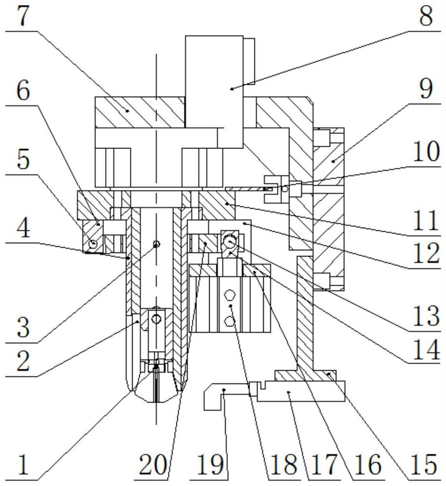
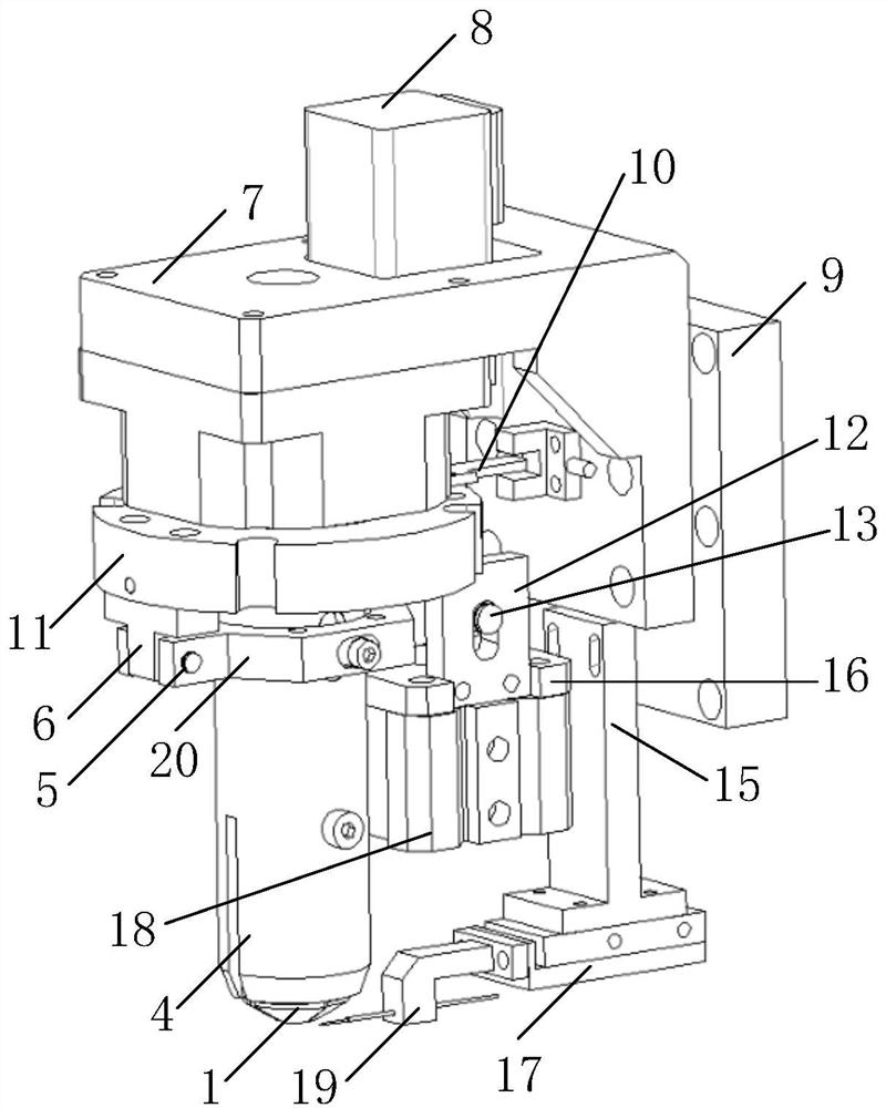
[0045] Embodiment 1 of the present invention provides a coupling Z-axis rotation device, such as Figure 2 to Figure 8 As shown, it includes a rotating part, a locking part, and a clamping part; the clamping part is arranged on the rotating part, and the locking part is arranged on the rotating part; the rotating part is used to rotate the The locking part and the clamping part; the clamping part is used to clamp the optical device, and the clamping part includes an upper locking mouth 1 and an upper chuck fixing sleeve 4, and the upper locking mouth 1 is provided with an elastic fiber The insert 1-2, the end face of the elastic fiber insert 1-2 is used to contact the end face of the optical device; the upper chuck inner sleeve 2 of the locking part is embedded in the upper chuck fixing sleeve 4 and The upper locking mouths 1 can move up and down, and the upper chuck inner sleeve 2 is used to lock the upper locking mouths 1 when going down.
[0046] The coupling Z-axis rotati...
Embodiment 2
[0051] Embodiment 2 of the present invention provides a coupling Z-axis rotation device, such as Figure 2 to Figure 8 As shown, it includes a rotating part, a locking part, and a clamping part; the clamping part is arranged on the rotating part, and the locking part is arranged on the rotating part; the rotating part is used to rotate the The locking part and the clamping part; the clamping part is used to clamp the optical device, and the clamping part includes an upper locking mouth 1 and an upper chuck fixing sleeve 4, and the upper locking mouth 1 is provided with an elastic fiber The insert 1-2, the end face of the elastic fiber insert 1-2 is used to contact the end face of the optical device; the upper chuck inner sleeve 2 of the locking part is embedded in the upper chuck fixing sleeve 4 and The upper locking mouth 1 can move up and down, and the second light hole 4-1 is used to lock the upper locking mouth 1 when the inner sleeve 2 of the upper chuck is going down.
...
PUM
 Abstract
Description
Claims
Application Information