Manufacturing method and structure of segmented skewed pole permanent magnet motor rotor

A technology of permanent magnet motor and manufacturing method, which is applied to the shape/pattern/structure of magnetic circuit, motor, and rotating parts of magnetic circuit, etc., can solve the problems of decreasing motor efficiency, increasing eddy current loss, and low yield, and improving efficiency , Improve the adaptability, the effect of high yield

Pending Publication Date: 2022-05-27
JSCC AUTOMATION XIAMEN
View PDF0 Cites 0 Cited by
  • Summary
  • Abstract
  • Description
  • Claims
  • Application Information

AI Technical Summary

Problems solved by technology

[0003] The deflection angle of each section of the conventional permanent magnet rotor segmented oblique pole process needs to be positioned by special tooling during riveting. The riveting holes need to be opened later or riveted after the waist-shaped holes are preset. The process is cumbersome and the yield is low.
If the lamination welding process is used, the eddy current loss will be increased, resulting in a decrease in motor efficiency

Method used


Image

  • Manufacturing method and structure of segmented skewed pole permanent magnet motor rotor
  • Manufacturing method and structure of segmented skewed pole permanent magnet motor rotor
  • Manufacturing method and structure of segmented skewed pole permanent magnet motor rotor

Examples


Embodiment 1

[0050] like Figure 1 to Figure 8 As shown, the present invention discloses a method for manufacturing a segmented inclined-pole permanent magnet motor rotor. This embodiment further describes the details of the manufacturing method by taking an embedded permanent magnet synchronous motor rotor with six poles 2p as an example. Include the following steps:

[0051] Making a punching unit:

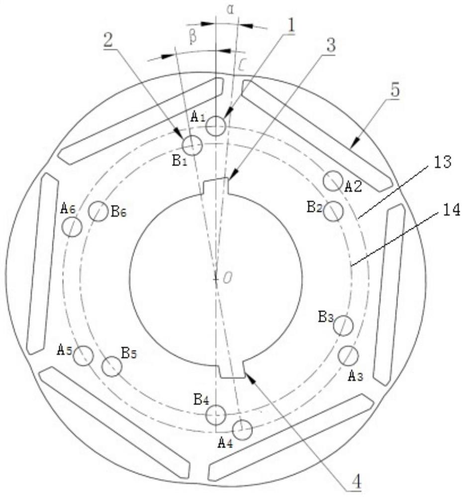
[0052] S1. Six radial magnetic steel assembling grooves 5 are dug at equal intervals on the punching piece body, and the two adjacent magnetic steel assembling grooves 5 are symmetrical to each other, and a rotating shaft hole is provided in the middle of the punching piece body.

[0053] S2. Make an outer layer arrangement circle 13 and an inner layer arrangement circle 14 between the magnetic steel assembly groove 5 and the shaft hole. Preferably, the distance between the edge of the outer layer riveting hole 1 and the edge of the inner layer riveting hole 2 is greater than or equal to 1...

Embodiment 2

[0071] like Figure 7 , Figure 8 As shown in the figure, the present invention discloses a manufacturing method of a segmented inclined pole permanent magnet motor rotor. further description.

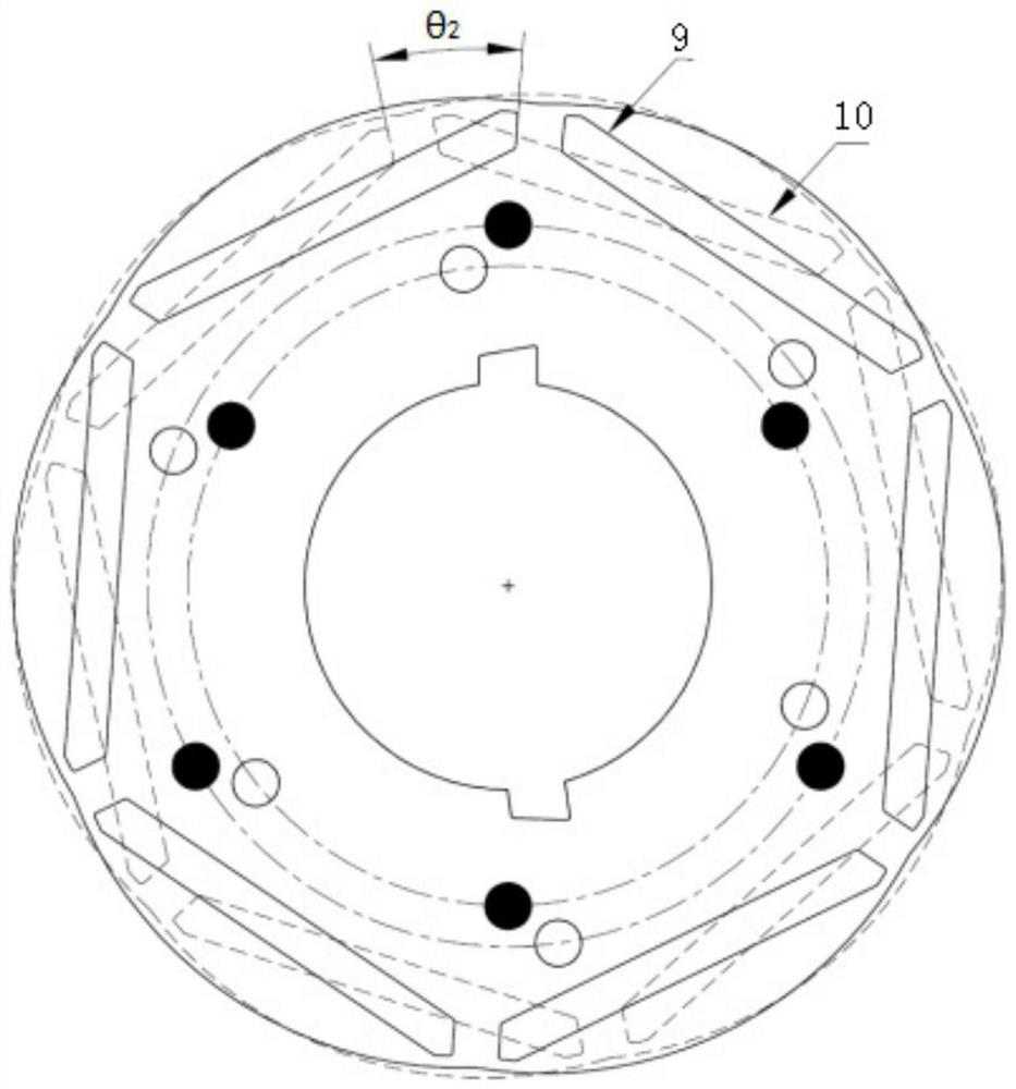
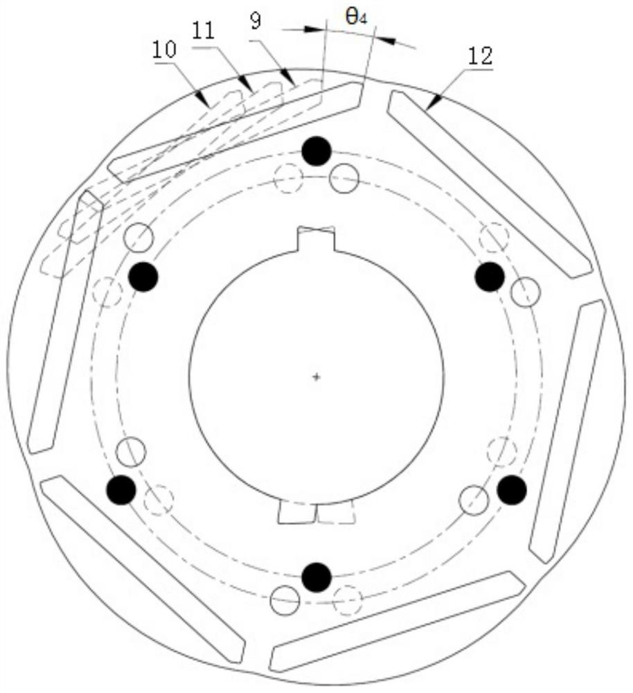
[0072] The punching unit is provided with four sections, which are marked as the first punching unit 9, the second punching unit 10, the third punching unit 11 and the fourth punching unit 12; from top to bottom, the fourth punching unit 12 , The first punching unit 9, the third punching unit 11, and the second punching unit 10 are stacked in sequence.

[0073] First, take out the third punching unit 11 and turn it over, place it under the first punching unit 9 , and rotate it to the first punching slot 3 of the third punching unit 11 and the first punching unit 9 . The centerlines of slot 3 are aligned.

[0074] Take out the second punching unit 10 and turn it over, place it under the third punching unit 11 , and rotate it to the second punching slot 4 of the second punching unit ...

Embodiment 3

[0080] like Figure 1 to Figure 8 As shown, the present invention also discloses a rotor structure of a segmented slanted pole permanent magnet motor, which is manufactured by the method for manufacturing a segmented slanted pole permanent magnet motor rotor in Embodiment 1 or Embodiment 2, and includes a plurality of punching units, Several sections of punching units are stacked at a preset oblique angle, and rivets 6 pass through the inner riveting holes 2 and the outer riveting holes 1 that are connected to several sections of punching units to fix them as a whole to form a motor rotor structure.

[0081] In order to reduce the magnetic leakage of the magnetic steel 7 in the adjacent two segments and improve the efficiency of the permanent magnet motor, a magnetic isolation layer 8 is arranged between the two adjacent punching units, and the magnetic isolation layer 8 is provided with the inner layer riveting holes 2 and 2. The connecting holes connected with the outer rive...


PUM


Abstract

The invention relates to the field of motors, and discloses a method for manufacturing a segmented skewed pole permanent magnet motor rotor, which comprises the following steps of: S1, manufacturing a punching sheet unit: digging a magnetic steel assembling groove matched with a magnetic steel arrangement mode, a rotating shaft hole, inner and outer layers of riveting holes designed in a staggered manner and a sheet arranging groove used for replacing positioning of a positioning tool in the punching sheet unit; and S2, assembling the punching sheet units, overlapping the punching sheet units by adopting a specific stacking mode, and fixing the punching sheet units into a whole by using rivets. The invention further discloses a segmented skewed pole permanent magnet motor rotor structure which is manufactured by the method. According to the invention, the punching sheet units with preset riveting holes and sheet arranging grooves are adopted, and riveting can be directly carried out after the punching sheet units adopt a specific stacking mode, so that the deflection angle precision of each section and the simplicity and convenience of the process are ensured, and the yield and the production efficiency are also improved.

Description

technical field [0001] The invention relates to the field of motors, in particular to a method for manufacturing a rotor of a segmented inclined pole permanent magnet motor and a structure thereof. Background technique [0002] In the permanent magnet motor, the interaction between the permanent magnet and the armature core cogging will generate cogging torque. If no suppression measures are taken, torque ripple will be generated, causing vibration and noise and affecting the control accuracy of the system. For the inner rotor permanent magnet motor, in order to reduce the cogging torque and improve the control performance, the stator inclined slot method or the rotor inclined pole method is often used. However, the stator inclined slot method has the disadvantage that it is difficult to realize automatic wire embedding. In mass-produced permanent magnet motors, the rotor inclined pole scheme is often used: that is, the combination of the stator straight slot and the rotor i...

Claims


Application Information

Patent Timeline
Patent Type & Authority Applications(China)
IPC IPC(8): H02K1/276H02K1/28H02K1/22H02K15/03
CPCH02K1/276H02K1/28H02K1/22H02K15/03Y02T10/64
Inventor 丁挺
Owner JSCC AUTOMATION XIAMEN
Why Eureka
Try Eureka