Efficient injection molding machine

An injection molding machine, high-efficiency technology, applied in the field of injection molding, can solve the problems of long cooling time, long stroke energy loss, low product efficiency, etc., to achieve the effect of shortening the molding cycle, improving molding efficiency, and improving injection molding efficiency

Inactive Publication Date: 2019-04-12
江苏东弘塑业有限公司
View PDF5 Cites 8 Cited by
  • Summary
  • Abstract
  • Description
  • Claims
  • Application Information

AI Technical Summary

Problems solved by technology

In the prior art, a single-mold injection molding machine is generally used, which has a long cooling time and low product efficiency. Even if multiple molds are used, multiple molds need to be preheated and cooled separately, which consumes a lot of energy, and multiple molds are formed into a series circuit. When preheating or cooling is performed at the same time, energy is often lost due to a long stroke, and the temperature control efficiency is low

Method used


Image

  • Efficient injection molding machine
  • Efficient injection molding machine
  • Efficient injection molding machine

Examples


Embodiment Construction

[0021] The following will clearly and completely describe the technical solutions in the embodiments of the present invention with reference to the accompanying drawings in the embodiments of the present invention. Obviously, the described embodiments are only some, not all, embodiments of the present invention. Based on the embodiments of the present invention, all other embodiments obtained by persons of ordinary skill in the art without making creative efforts belong to the protection scope of the present invention.

[0022] In the description of the present invention, it should be understood that the orientations or positional relationships indicated by "front", "rear", "left", "right", "upper" and "lower" in terms are based on those shown in the accompanying drawings. Orientation or positional relationship is only for the convenience of describing the present invention and simplifying the description, and does not indicate or imply that the device or element referred to mu...


PUM


Abstract

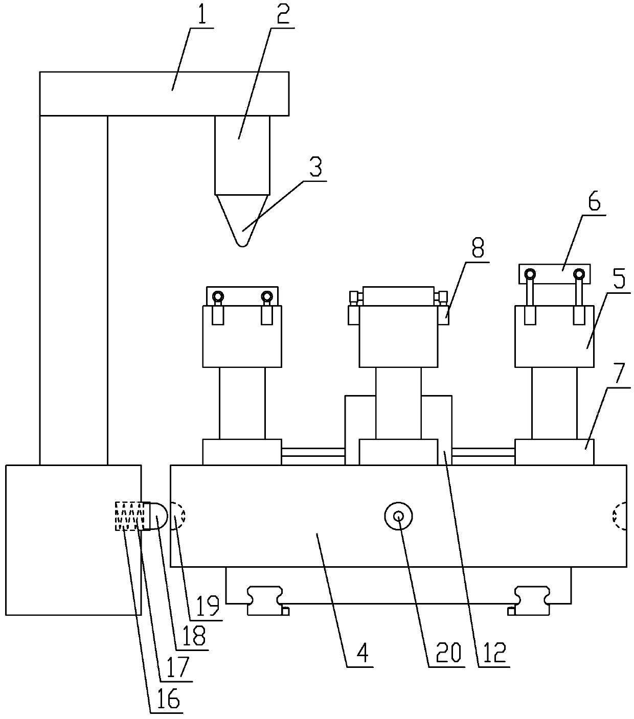
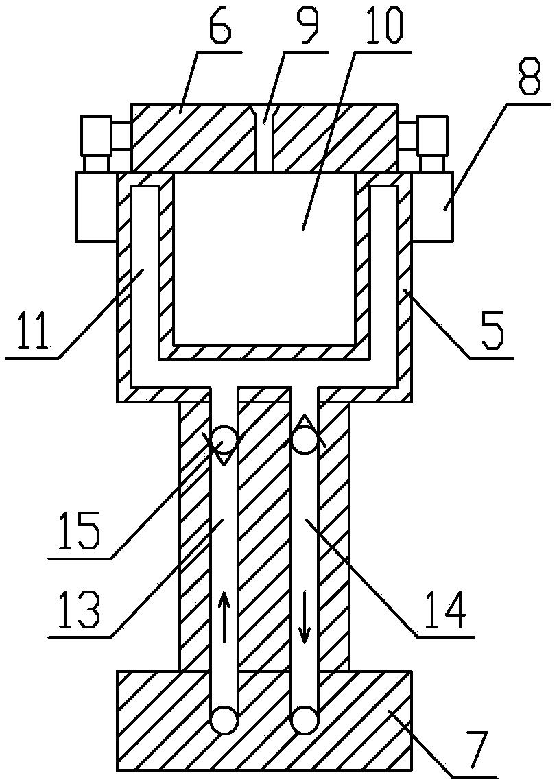
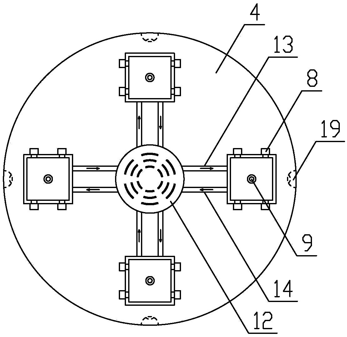
The invention provides an efficient injection molding machine. The efficient injection molding machine comprises an injection molding unit and a mold unit. The injection molding unit comprises a fixedframe, a telescopic piece and an injection molding head; and the mold unit comprises a rotary table, a plurality of forming molds and temperature control assemblies. Each forming mold comprises a lower mold and an upper mold, wherein the lower mold is fixedly connected with the rotary table, and the upper mold is movably connected with the lower mold; and each upper mold is provided with an injection molding hole, and each lower mold is provided with an injection molding cavity and a temperature control cavity for preheating and cooling the injection molding cavity. Each temperature control assembly comprises a cool-warm air heating radiator, an air inlet pipe and an air outlet pipe, and the air inlet pipes and the air outlet pipes communicate the cool-warm air heating radiators with thetemperature control cavities. The fixed frame is further provided with a positioning assembly for ensuring the alignment of the injection molding holes and the injection molding head. According to theefficient injection molding machine, the forming molds are arranged on the rotary table, so that the injection molding head can continuously work, and the injection molding efficiency is improved; and the forming molds communicate with the cool-warm air heating radiators correspondingly, hot air or cold air is conveyed into the molds through the cool-warm air heating radiators, so that the multiple forming molds are preheated or cooled at the same time, the forming period is shortened, and the forming efficiency is improved.

Description

technical field [0001] The invention relates to the field of injection molding, in particular to a high-efficiency injection molding machine. Background technique [0002] Injection molding machine is a tool for producing plastic products, and it is also a tool for giving plastic products a complete structure and precise dimensions. Injection molding is to inject heated and melted plastic into the injection mold cavity under high pressure from the injection molding machine, and obtain molded products after cooling and solidification; In the injection molding process, the mold temperature will affect the shrinkage, deformation, fusion line, surface gloss and other appearance quality of the plastic product and the characteristics of the molding cycle; in general molding conditions, the mold must be maintained at At a certain temperature, prevent the molten material from cooling and forming prematurely, causing quality problems such as faults in the materials injected before an...

Claims


Application Information

Patent Timeline
Patent Type & Authority Applications(China)
IPC IPC(8): B29C45/06B29C45/17B29C45/67B29C45/73B29C45/78
CPCB29C45/062B29C45/1742B29C45/67B29C45/7312B29C45/7337B29C45/78B29C2045/067B29C2945/76531B29C2945/76735
Inventor 夏春翠
Owner 江苏东弘塑业有限公司
Why Eureka
Try Eureka