
A pile pulling device

A technology of internal gear and bottom plate, applied in sheet pile wall, construction, infrastructure engineering and other directions, can solve the problems of inconvenience of staff, delay in construction period, and inability to directly bind in the past, so as to reduce the risk factor and avoid danger. Effect

Active Publication Date: 2021-06-01
王树华
View PDF0 Cites 0 Cited by
  • Summary
  • Abstract
  • Description
  • Claims
  • Application Information

AI Technical Summary

Problems solved by technology

[0004] The invention provides a pile pulling device, which aims to solve the problem that the existing pile pulling device on a ship uses a cable or a ferrule to be manually set on the outer surface of the round pile when the pile pulling device is pulling out the round pile. Large or located in the water, the staff is inconvenient or unable to go directly to the binding, resulting in delays in the construction period and other problems

Method used


Image

  • A pile pulling device
  • A pile pulling device
  • A pile pulling device

Examples


Embodiment Construction

[0017] In order to make the object, technical solution and advantages of the present invention clearer, the present invention will be further described in detail below in conjunction with the accompanying drawings and embodiments. It should be understood that the specific embodiments described here are only used to explain the present invention, not to limit the present invention.

[0018] In describing the present invention, it should be understood that the terms "length", "width", "upper", "lower", "front", "rear", "left", "right", "vertical", The orientation or positional relationship indicated by "horizontal", "top", "bottom", "inner", "outer", etc. are based on the orientation or positional relationship shown in the drawings, and are only for the convenience of describing the present invention and simplifying the description, rather than Nothing indicating or implying that a referenced device or element must have a particular orientation, be constructed, and operate in a ...


PUM


Abstract

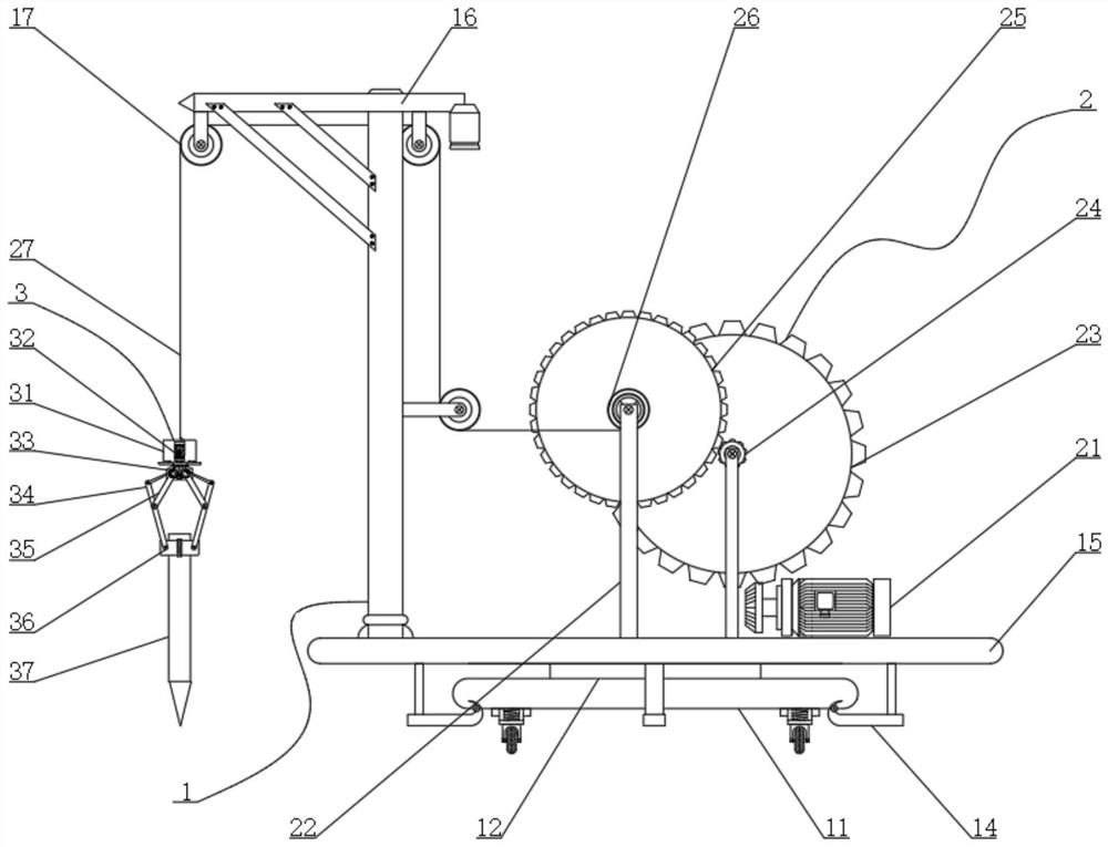
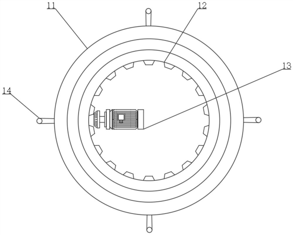
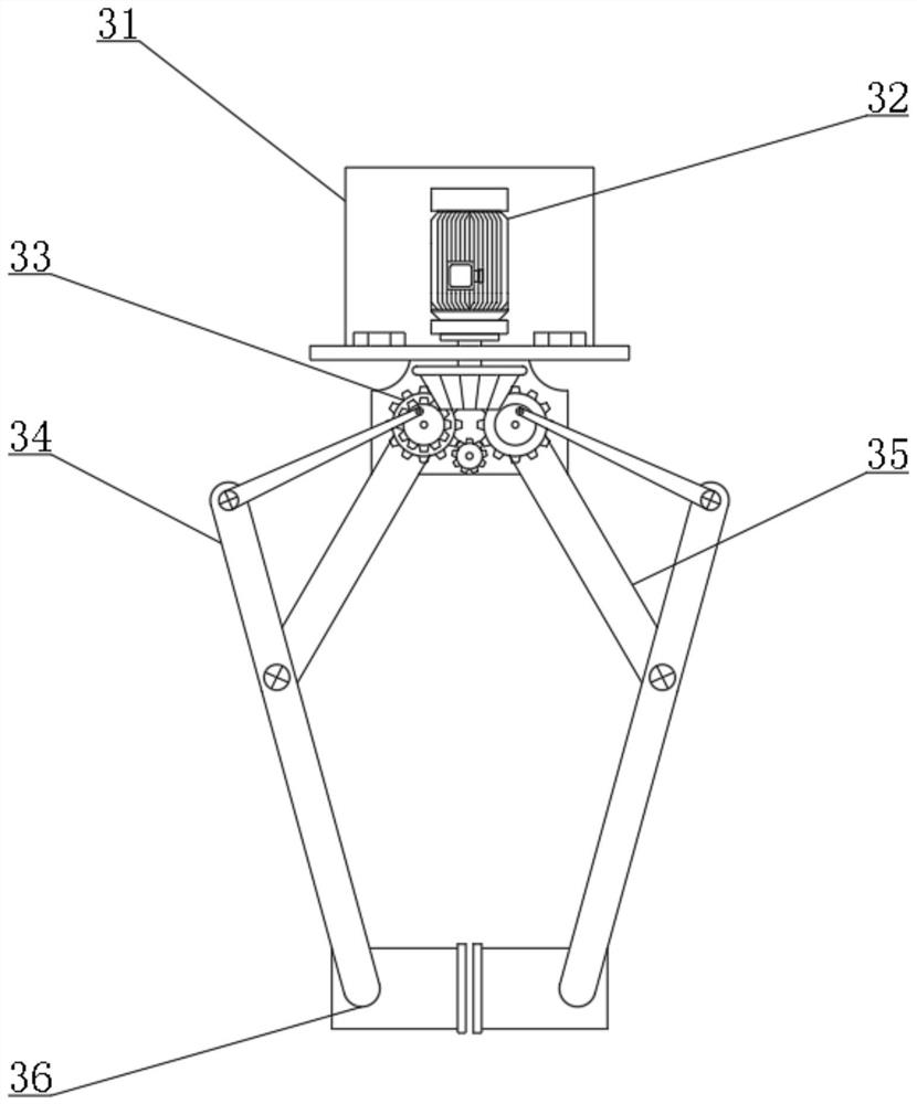
The invention discloses a pile pulling device, which comprises a chassis assembly, a traction assembly and a clamping assembly. The base, the internal gear is located inside the base, and the output shaft of the rotating motor is engaged with the internal gear; firstly, the traction motor drives the main gear to rotate, and the main gear passes through the transmission wheel Drive the pinion gear and the rope winding shaft to rewind or release the traction rope, and then adjust the position of the clamping assembly and lift and pull out the round pile. The power motor passes through the The gear set adjusts the angle between the main branch and the auxiliary branch, thereby adjusting the opening distance of the clamp ring on the left and right sides, and then clamping the round pile, reducing the overall work The risk factor in the process avoids the danger of the staff.

Description

technical field [0001] The invention belongs to the technical field of machinery, and in particular relates to a pile pulling device. Background technique [0002] The mechanical method of pulling piles, that is, the electric motor drives the hoist, and the pulling force of the wire rope pulley block is used to force the piles out of the ground. It is easy to use and low in cost, but the pile pulling force is not large, the equipment is heavy, and the pile pulling efficiency is low. It is suitable for soft soil strata construction. [0003] In the extraction of circular piles, the existing pile pulling devices on ships use cables or ferrules to be placed on the outer surface of the circular piles manually. Because some piles are large in size or located in water, it is inconvenient for the staff or unable to directly Binding in the past caused delays in the construction period, etc. Contents of the invention [0004] The invention provides a pile pulling device, which ai...

Claims


Application Information

Patent Timeline
Patent Type & Authority Patents(China)
IPC IPC(8): E02D9/02
CPCE02D9/02
Inventor 王树华
Owner 王树华
Learn More