Multifunctional electronic sphygmomanometer

An electronic sphygmomanometer and multi-functional technology, applied in the field of sphygmomanometers, can solve the problems of increasing the labor burden of the staff, cumbersome disassembly and disassembly process, and affecting the detection effect, so as to reduce the growth of bacteria, reduce fatigue and improve work efficiency. Effect

Pending Publication Date: 2021-12-03
奚愉康
View PDF1 Cites 0 Cited by
  • Summary
  • Abstract
  • Description
  • Claims
  • Application Information

AI Technical Summary

Problems solved by technology

[0004] 1. Although the arm-type electronic sphygmomanometer that ensures the cleaning of the wristband can be disassembled and separated from the sphygmomanometer, it is convenient to clean the wristband, but there are still deficiencies. The disassembly and assembly process for cleaning the device is cumbersome and time-consuming It is laborious, increases the labor burden of the staff, and has low practicability;
[0005] 2. The general arm-type electronic sphygmomanometer usually has a separate structure for the wristband and the main body. The wristband is separately configured and packaged. People usually put the wristband aside after use, take it out when using it, and then wear it through the cuff For detection; when the sphygmomanometer is detected, the user's arm must be inclined, and the user needs to wrap the wristband directly around the user's arm, and then use the Velcro to bind the cuff. The Velcro is sticky after long-term use. The detection effect is affected by the loose binding of the descending cuff

Method used


Image

  • Multifunctional electronic sphygmomanometer
  • Multifunctional electronic sphygmomanometer
  • Multifunctional electronic sphygmomanometer

Examples


Embodiment Construction

[0026] The following will clearly and completely describe the technical solutions in the embodiments of the present invention with reference to the accompanying drawings in the embodiments of the present invention. Obviously, the described embodiments are only some, not all, embodiments of the present invention. Based on the embodiments of the present invention, all other embodiments obtained by persons of ordinary skill in the art without making creative efforts belong to the protection scope of the present invention.

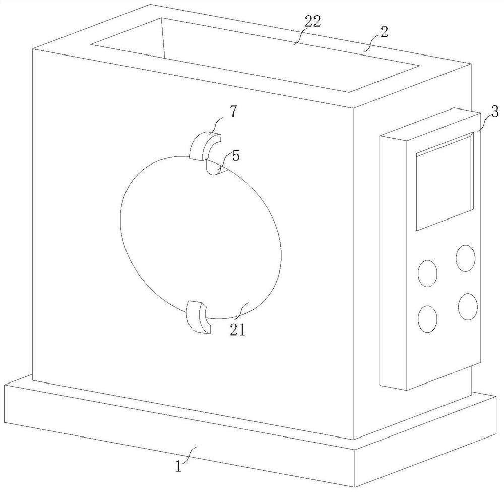
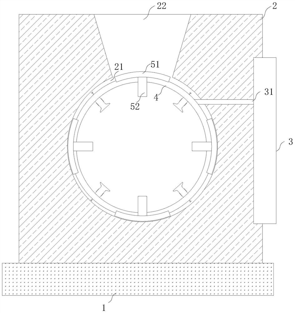
[0027] see Figure 1 to Figure 6 , the present invention provides a technical solution:

[0028] A multifunctional electronic sphygmomanometer, such as Figure 1 to Figure 3 As shown, it includes a base plate 1, a support frame 2 and a display screen 3, the base plate 1 is fixedly installed at the lower end of the support frame 2, and the support frame 2 is designed in a rectangular structure, and the display screen 3 is fixedly installed at the bottom of the...


PUM


Abstract

The invention relates to the technical field of sphygmomanometers, in particular to a multifunctional electronic sphygmomanometer. The multifunctional electronic sphygmomanometer comprises a bottom plate, a supporting frame and a display screen, wherein the bottom plate is fixedly mounted at the lower end of the supporting frame, the supporting frame is designed to be of a rectangular structure, the display screen is fixedly mounted on the right side of the supporting frame, and an air inlet pipe is fixedly connected to the inner part of the display screen and the supporting frame; a circular groove is formed in the middle of the inner part of the supporting frame, the circular groove is inclined by 20-25 degrees, a fan-shaped groove is formed in the position, close to the upper end of the circular groove, of the inner part of the supporting frame, the lower end of the fan-shaped groove communicates with the middle part of the upper end of the circular groove, and a clamping assembly is movably mounted in the circular groove; and the clamping assembly comprises an inner ring, abutting bags, an inner ring pipe and four limiting assemblies. According to the sphygmomanometer, the inner part of the sphygmomanometer body can be disinfected without disassembling the sphygmomanometer body, bacterium breeding and wearing procedures are reduced, fatigue caused by long-time oblique placement of arms is relieved, and the working efficiency is improved.

Description

technical field [0001] The invention relates to the technical field of sphygmomanometers, in particular to a multifunctional electronic sphygmomanometer. Background technique [0002] With the improvement of living standards, people pay more and more attention to health. As the most important life parameter of human health, blood pressure is an important basis for clinical diagnosis of diseases, observation of treatment effects, and prognosis judgment. Medical care, especially the monitoring of critically ill patients and patients under general anesthesia, is of great significance; and sphygmomanometers are used among different users. The belt is cleaned and disinfected to reduce the growth of bacteria. [0003] The existing patent (notification number: CN213309698U) is an arm-type electronic sphygmomanometer that ensures the wristband is clean. There are a setting key, an on / off key and a memory key. The main body of the sphygmomanometer is provided with an adjustment key...

Claims


Application Information

Patent Timeline
Patent Type & Authority Applications(China)
IPC IPC(8): A61B5/0225A61L2/18A61L2/26A61L101/34
CPCA61B5/0225A61B5/02141A61L2/18A61L2/26A61L2202/15A61L2202/24A61L2101/34
Inventor 奚愉康王金雨
Owner 奚愉康
Why Eureka
Try Eureka