Beam-column joint structure and mounting method thereof

A technology of beam-column joints and columns, which is applied in the direction of building construction and construction, can solve problems affecting the strength of columns, easy to tear steel pipes, and small stress-bearing parts, so as to improve connection stability, increase connection strength, The effect of improving stability

Active Publication Date: 2019-04-12
台州航权机械科技有限公司
View PDF5 Cites 2 Cited by
  • Summary
  • Abstract
  • Description
  • Claims
  • Application Information

AI Technical Summary

Problems solved by technology

[0002] In the existing beam-column structure that uses a hollow tube as the column, the end of the beam is generally connected directly to the outer wall of the column. Since the outer wall of the column is arc-shaped, the direct connection will result in a very small stress-bearing part, which is easy to tear the steel tube or cause damage. The steel pipe is deformed and the connection strength is low
[0003] Therefore, generally, each beam body is reinforced and installed on the outside of the column through connecting pieces, but this will affect the appearance of the outside of the column, and after being installed through independent connecting pieces, the strength of the connecting node will be skewed; or directly the column The body is divided into two sections of structure, and the end of the beam body is fixed between the two sections of columns, but it will affect the strength of the column, so it is necessary to improve

Method used


Image

  • Beam-column joint structure and mounting method thereof
  • Beam-column joint structure and mounting method thereof
  • Beam-column joint structure and mounting method thereof

Examples


Embodiment Construction

[0048] The following are specific embodiments of the present invention and in conjunction with the accompanying drawings, the technical solutions of the present invention are further described, but the present invention is not limited to these embodiments.

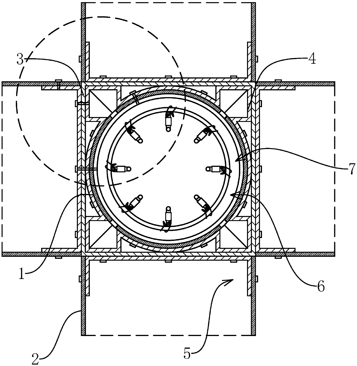
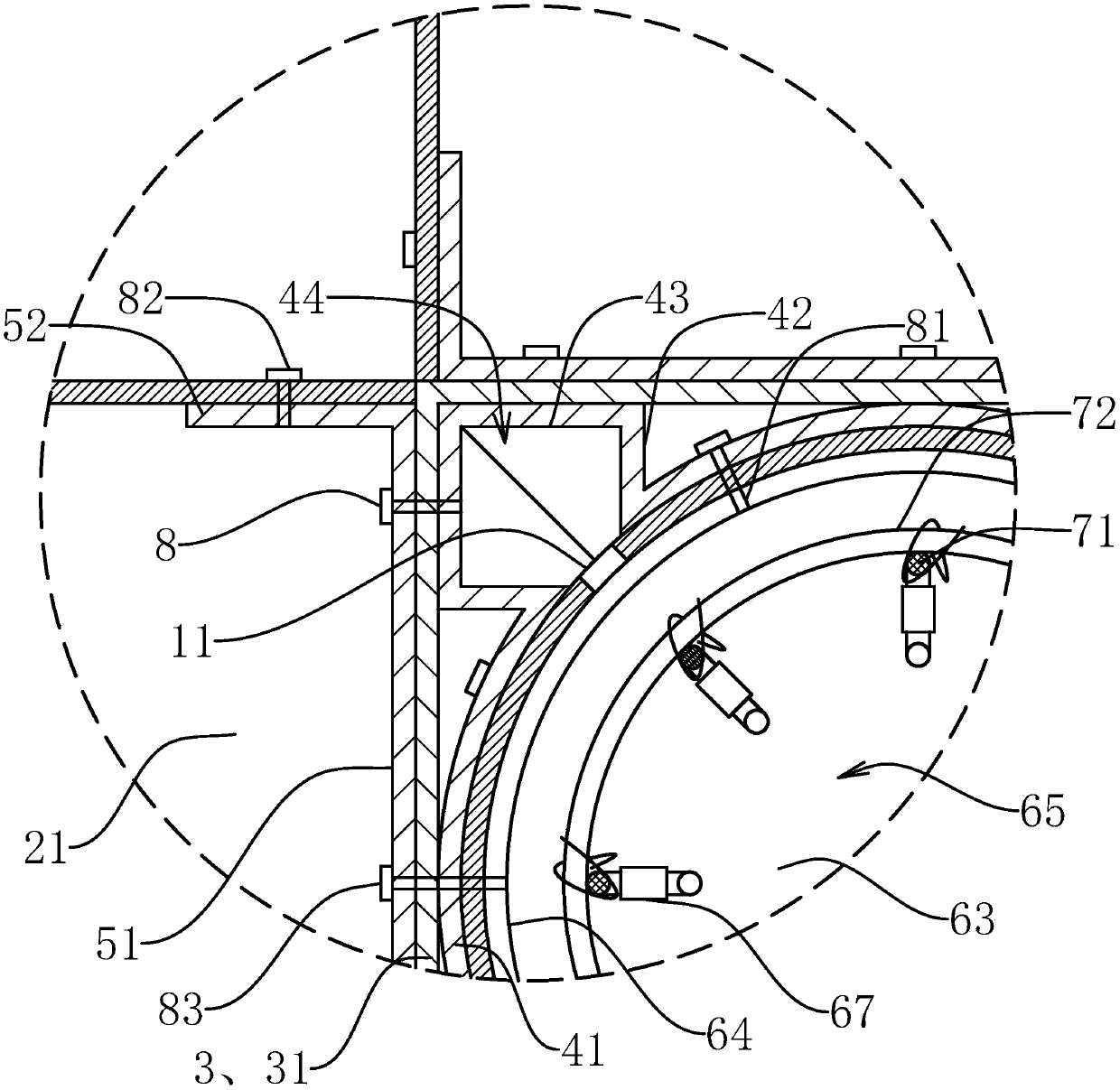
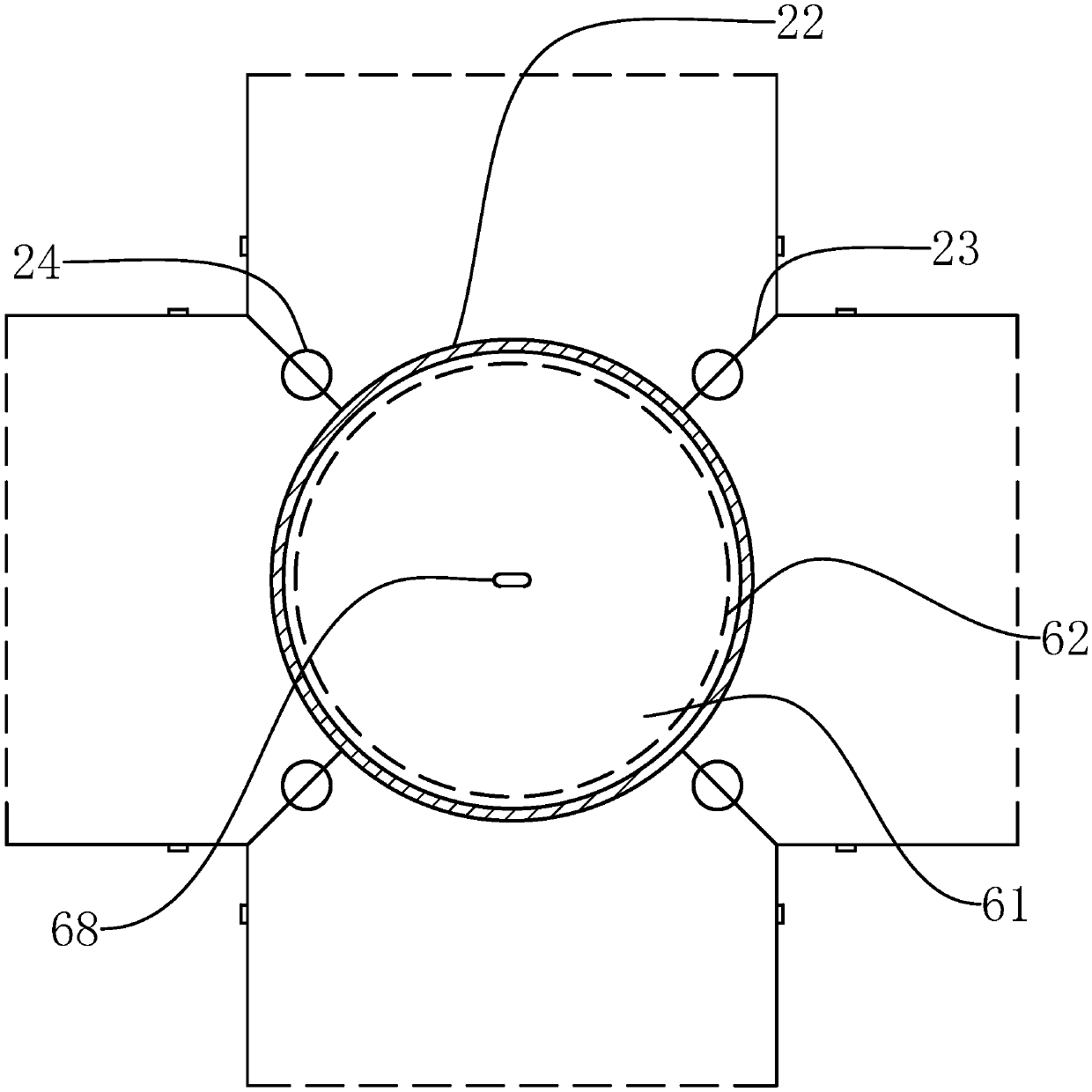
[0049] like Figure 1-4 As shown, a beam-column node structure of the present invention includes a vertically arranged column body 1 and a horizontally arranged beam body 2, the column body 1 and the beam body 2 are respectively a hollow circular tube structure and a hollow rectangular tube structure, and also includes a hollow The connecting pipe 3 of the square pipe structure, the connecting pipe 3 is set on the outside of the cylinder 1, and connected to the cylinder 1 through the connecting piece 4, the connecting pipe 3 includes four connecting plates 31 connected in sequence, and the connecting plate 31 is connected to the cylinder 1 axis parallel;

[0050] The connecting piece 4 is integrally formed by bending a st...


PUM


Abstract

The invention provides a beam-column joint structure and a mounting method thereof, and belongs to the field of steel structures. The problem that the existing beam-column connecting strength is low is solved. The beam-column joint structure comprises a column body and four beam bodies, the column body is a circular tube, and the beam bodies are square tubes; the beam-column joint structure further comprises square tube connecting tubes, the connecting tubes sleeve the outer side of the column body and are connected with the column body through connecting pieces, each connecting tube comprisesfour connecting plates, the connecting pieces are formed in an integrated bending mode and each comprises four internal-connecting plates and four corner connection pieces, and each corner connectionpiece comprises two connection plates and two external-connecting plates; the beam-column joint structure further comprises four steel channel connecting seats, and each connecting seat comprises a bottom plate and two side plates; the beam-column joint structure further comprises a pouring seat located in the column body, the pouring seat comprises an upper baffle and a lower baffle, the upper baffle and the lower baffle are connected through a reinforcement cage, and an upper connecting ring and a lower connecting ring are fixed to the bottom face of the upper baffle and the top face of thelower baffle correspondingly; and the four beam bodies sleeve the four connecting seats in a matched mode. According to the beam-column joint structure, the beam-column connecting strength and stability can be improved.

Description

technical field [0001] The invention belongs to the technical field of steel structures, and relates to a beam-column node structure and an installation method thereof. Background technique [0002] In the existing beam-column structure using a hollow circular tube as the column, the end of the beam is generally directly connected to the outer wall of the column. Since the outer wall of the column is arc-shaped, the direct connection will result in a very small stress-bearing part, which is easy to tear the steel tube or cause damage. The steel pipe is deformed and the connection strength is low. [0003] Therefore, generally, each beam body is reinforced and installed on the outside of the column through connecting pieces, but this will affect the appearance of the outside of the column, and after being installed through independent connecting pieces, the strength of the connecting node will be skewed; or directly the column The body is divided into two sections of structu...

Claims


Application Information

Patent Timeline
IPC IPC(8): E04B1/58
CPCE04B1/185
Inventor 张丽丽
Owner 台州航权机械科技有限公司
Why Eureka
Try Eureka