A stable beam-column connection structure and installation method thereof

A technology for connecting structures and beams and columns, applied in building structures, buildings, etc., can solve the problems of small stressed parts, affecting the strength of columns, and the strength skewness of connecting nodes, and achieve the effect of improving vertical bearing capacity

Active Publication Date: 2020-12-04
台州航权机械科技有限公司
View PDF10 Cites 0 Cited by
  • Summary
  • Abstract
  • Description
  • Claims
  • Application Information

AI Technical Summary

Problems solved by technology

[0002] In the existing beam-column structure that uses a hollow tube as the column, the end of the beam is generally connected directly to the outer wall of the column. Since the outer wall of the column is arc-shaped, the direct connection will result in a very small stress-bearing part, which is easy to tear the steel tube or cause damage. The steel pipe is deformed and the connection strength is low
[0003] Therefore, generally, the end of the beam body is directly reinforced and installed on the outside of the column through other connectors, but it will affect the appearance of the outside of the column, and the strength of the connection node is skewed; or the column is directly divided into two sections, and the end of the beam is fixed in two sections Between the columns, but it will affect the strength of the columns, so it is necessary to improve

Method used


Image

  • A stable beam-column connection structure and installation method thereof
  • A stable beam-column connection structure and installation method thereof
  • A stable beam-column connection structure and installation method thereof

Examples


Embodiment Construction

[0055] The following are specific embodiments of the present invention and in conjunction with the accompanying drawings, the technical solutions of the present invention are further described, but the present invention is not limited to these embodiments.

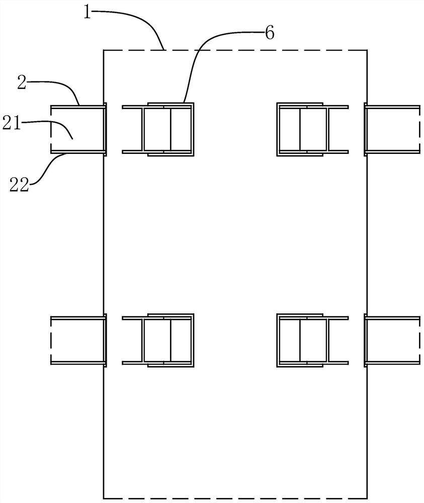
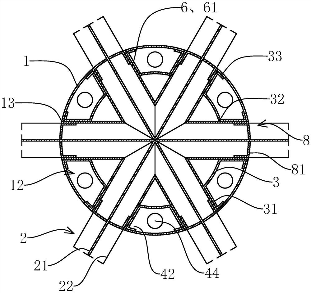
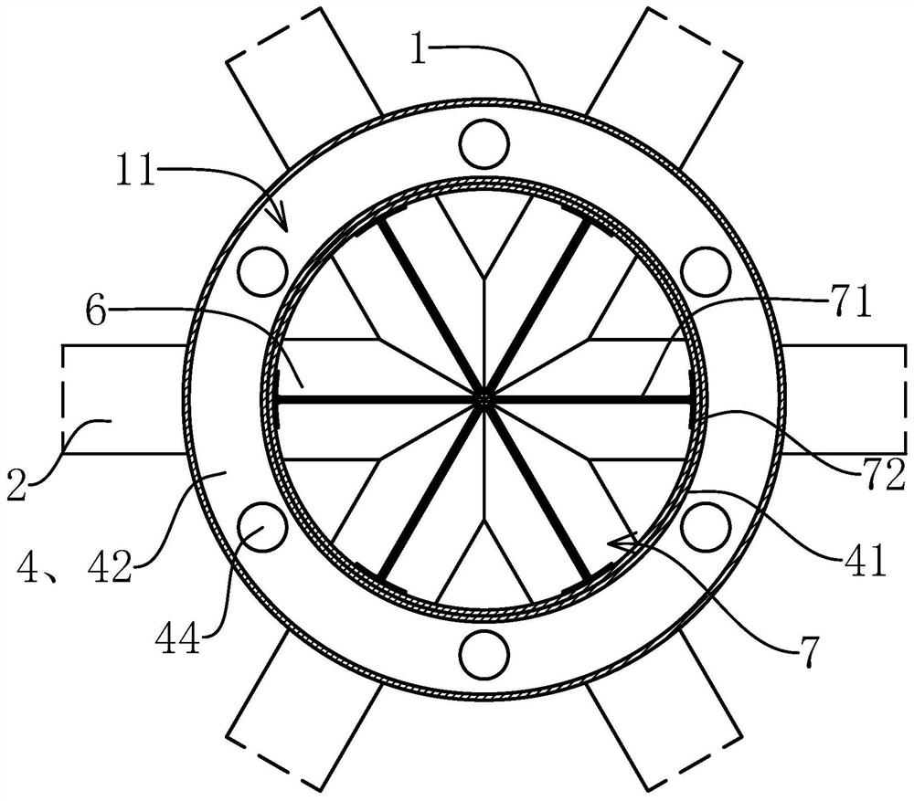
[0056] Such as Figure 1-5 As shown, a stable beam-column connection structure of the present invention includes a vertically arranged column body 1 and a horizontally arranged beam body 2, the column body 1 and the beam body 2 are respectively a hollow circular tube structure and an I-shaped steel structure, and the column body The body 1 is coaxially provided with a central tube 3 with a hollow circular tube structure, and the cylinder 1 and the central tube 3 are provided with a number of connection nodes distributed along the axial direction of the cylinder 1. The connection nodes include two sleeves on the central tube 3. A connecting piece 4, the connecting piece 4 includes a circular sleeve-shaped connecting sleeve ...


PUM


Abstract

The invention provides a stable beam-column connecting structure and a mounting method thereof, and belongs to the field of steel structures. The problem that the existing beam-column connecting strength is low is solved. The stable beam-column connecting structure comprises a column body and bema bodies, the column body is internally provided with a hollow circular tube center tube, a plurality of connecting joints are arranged on the column body and the center tube, each connecting joint comprises two connecting pieces sleeving the center tube, and each connecting piece comprises a circular-sleeve-shaped connecting sleeve sleeving the outer side of the center tube in a matched mode, and further comprises an inner connecting plate and an outer connecting plate, the inner edges of the inner connecting plates and the inner edges of the outer connecting plates are fixed to the outer walls of the two ends of the connecting sleeve correspondingly, the outer edges of the inner connecting plates and the outer edges of the outer connecting plates are connected with the inner wall of the column body, a circular-ring-shaped main grouting cavity which is coaxial with the column body is formed by the connecting pieces and the column body in a defined mode, the column body is provided with a plurality of outer supporting holes, and an inner supporting hole is formed in the center tube; andthe stable beam-column connecting structure further comprises reinforcing seats located in the center tube, and the reinforcing seat is arranged between the every two adjacent connecting joints. According to the stable beam-column connecting structure, the beam-column connecting strength and stability can be improved.

Description

technical field [0001] The invention belongs to the technical field of steel structures, and relates to a stable beam-column connection structure and an installation method thereof. Background technique [0002] In the existing beam-column structure using a hollow circular tube as the column, the end of the beam is generally directly connected to the outer wall of the column. Since the outer wall of the column is arc-shaped, the direct connection will result in a very small stress-bearing part, which is easy to tear the steel tube or cause damage. The steel pipe is deformed and the connection strength is low. [0003] Therefore, the end of the beam body is usually directly reinforced and installed on the outside of the column through other connectors, but this will affect the appearance of the outside of the column, and the strength of the connection node is skewed; or the column is directly divided into two sections, and the end of the beam is fixed in two sections Between...

Claims


Application Information

Patent Timeline
Patent Type & Authority Patents(China)
IPC IPC(8): E04B1/58
CPCE04B1/185
Inventor 张丽丽
Owner 台州航权机械科技有限公司
Why Eureka
Try Eureka