
Manufacturing method of metal wire and array substrate, array substrate

A manufacturing method and metal wire technology, applied in the field of array substrates, can solve the problems of upper-span metal wire breakage, electrical failure, and large slope angle, etc., so as to facilitate metal cross-wire, relieve upper-span metal wire breakage, and improve product yield and display quality effects

Active Publication Date: 2020-09-08
HEFEI XINSHENG OPTOELECTRONICS TECH CO LTD +1
View PDF5 Cites 0 Cited by
  • Summary
  • Abstract
  • Description
  • Claims
  • Application Information

AI Technical Summary

Problems solved by technology

[0003] Since there are cross-line layouts in various situations such as gate and source-drain, gate and pixel electrode, source-drain and pixel electrode in the backplane process, various thick and narrow metal lines are required, and the metal lines The slope angle of the cross-section must be gentle enough, otherwise it is very easy to cause the upper span metal wire to break, resulting in various electrical failures
At present, the slope angle of the cross section of the conventionally etched metal line is relatively large, and the slope angle gradually increases with the increase of the thickness of the metal film, which is very easy to cause the breakage of the upper spanning metal line

Method used


Image

  • Manufacturing method of metal wire and array substrate, array substrate
  • Manufacturing method of metal wire and array substrate, array substrate
  • Manufacturing method of metal wire and array substrate, array substrate

Examples


Embodiment Construction

[0046] Example embodiments will now be described more fully with reference to the accompanying drawings. Example embodiments may, however, be embodied in many forms and should not be construed as limited to the embodiments set forth herein; rather, these embodiments are provided so that this application will be thorough and complete, and will fully convey the concept of example embodiments to those skilled in the art. The same reference numerals in the drawings denote the same or similar structures, and thus their detailed descriptions will be omitted.

[0047] Although relative terms such as "upper" and "lower" are used in this specification to describe the relative relationship of one component of an icon to another component, these terms are used in this specification only for convenience, for example, according to the description in the accompanying drawings directions for the example described above. It will be appreciated that if the illustrated device is turned over s...


PUM


Abstract

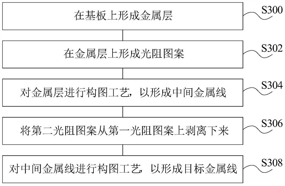
The invention relates to the technical field of display, in particular to a manufacturing method of a metal wire, a manufacturing method of an array substrate and the array substrate. The manufacturing method of the metal wire comprises the following steps of forming a metal layer on a substrate; forming a photoresist pattern on the metal layer, wherein the photoresist pattern comprises a first photoresist pattern and a second photoresist pattern located on the first photoresist pattern, and the orthographic projection of the first photoresist pattern on the metal layer is located in the orthographic projection of the second photoresist pattern on the metal layer; carrying out a patterning process in the metal layer to form a middle metal wire; stripping the second photoresist pattern fromthe first photoresist pattern; and carrying out a patterning process on the middle metal wire to form the metal wire. By virtue of the scheme, the gradient angle of the cross section of the metal wire can be reduced, so that the follow-up metal wire crossing is facilitated, and the product yield and the display quality are greatly improved.

Description

technical field [0001] The present application relates to the field of display technology, and in particular, relates to a method for manufacturing a metal wire, a method for manufacturing an array substrate, and the array substrate. Background technique [0002] With the gradual development of display products in the direction of large size, the metal wires of the display panel need to be more and more conductive, which requires the metal wires to be thick enough; at the same time, in order to meet high PPI (Pixels Per Inch, pixel density) and The requirement of high aperture ratio requires the metal wire to be narrow enough. That is to say, the current metal wire is gradually developing in the direction of thick and narrow. [0003] Since there are cross-line layouts in various situations such as gate and source-drain, gate and pixel electrode, source-drain and pixel electrode in the backplane process, various thick and narrow metal lines are required, and the metal lines ...

Claims


Application Information

Patent Timeline
Patent Type & Authority Patents(China)
IPC IPC(8): H01L21/768H01L23/528H01L27/12G03F7/00
CPCG03F7/00H01L21/76892H01L23/5283H01L27/1244
Inventor 刘宁
Owner HEFEI XINSHENG OPTOELECTRONICS TECH CO LTD
Learn More