
A method and equipment for improving the utilization rate of active material of the pole plate

A technology of active material and utilization rate, applied in the direction of lead-acid battery electrodes, etc., can solve the problems affecting the utilization rate of active material, low utilization rate of active material, and high utilization rate of active material, so as to improve the battery reserve capacity and improve the utilization of active material. rate, and the effect of improving market competitiveness

Active Publication Date: 2021-06-04
CAMEL GRP XIANGYANG BATTERY
View PDF0 Cites 0 Cited by
  • Summary
  • Abstract
  • Description
  • Claims
  • Application Information

AI Technical Summary

Problems solved by technology

[0002] The current production process is to alternately arrange positive plates, separators, and negative plates together to form an electrode group. This assembly structure will produce the following defects when the battery is used for a long time: ① The utilization rate of active materials on the upper part of the plate is higher than that on the lower part; ② Long-term use leads to electrolyte stratification; ③ According to the current transmission direction and current distribution, the resistance of the lower part of the plate is higher than that of the upper part of the plate.
The number of ions transported in the upper part of the polar plate is much larger than that in the lower part of the polar plate, which causes the active material in the upper part of the polar plate to soften earlier than the active material in the lower part of the polar plate. The lower utilization rate of the active material in the lower part of the polar plate also affects the overall active material utilization rate

Method used


Image

  • A method and equipment for improving the utilization rate of active material of the pole plate
  • A method and equipment for improving the utilization rate of active material of the pole plate
  • A method and equipment for improving the utilization rate of active material of the pole plate

Examples


Embodiment Construction

[0022] Below in conjunction with accompanying drawing and technical scheme, the present invention is described in further detail:

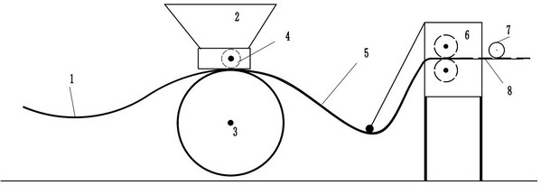
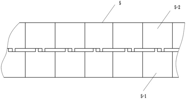
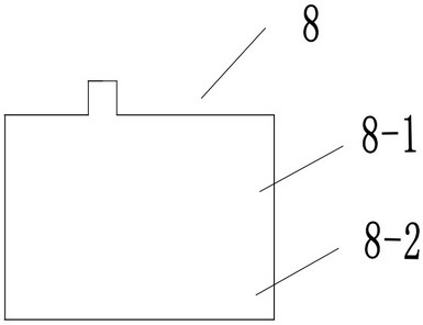
[0023] figure 1 Among them, it includes the frame of the coating and filling machine for producing wet plates, the coating and filling machine head 2 arranged above the frame and the wheel hub 3 below, the pressure roller 4 in the coating and filling machine head, and the slitting machine for cutting wet plates 6. A rubber pressure wheel 7 for reducing the deformation of the polar plate, and a cutting knife is arranged in the slitting machine 6 . The pressure roller 4 is located above the wheel hub 3, and the central axis of the pressure roller 4 is parallel to the central axis of the wheel hub 3; the roller surface of the pressure roller 4 includes a working section B and a non-working section A, and the non-working section A is located in the middle of the pressure roller 4 , the two ends of the non-working section A are symmetrically divided i...


PUM


Abstract

A method and equipment for improving the utilization rate of the active material of the pole plate; in the grid mesh belt coating and filling process, the pressure roller in the coating head is located above the wheel hub, and the central axis of the pressure roller is parallel to the central axis of the wheel hub; The roller surface of the pressure roller includes the working section B and the non-working section A. The roller surface of the working section B at both ends of the non-working section A is an inclined surface; The cutting machine cuts the wet raw plate belt to obtain the wet plate with the lead paste gradually decreasing from the upper part of the plate to the lower part of the plate; the wet plate is stacked in the curing frame; each frame has 4 layers, and the bakelite board is placed after stacking two layers; each layer 6 When stacking plates, the upper and lower stacks of wet plates are stacked in opposite directions, and the number of plates in each stack is 30-40 pieces of wet plates; after curing and drying, the thickness of the upper part of the obtained plate is 0.05-0.5mm thicker than that of the lower part. In the present invention, by changing the distribution of the lead paste on the polar plate, the lead paste from the upper part of the polar plate to the lower part of the polar plate is gradually reduced, thereby improving the utilization rate of the overall active material of the polar plate.

Description

technical field [0001] The invention belongs to the technical field of lead-acid storage batteries, and in particular relates to a method and equipment for improving the utilization rate of active materials in the polar plates of flooded storage batteries. Background technique [0002] The current production process is to alternately arrange positive plates, separators, and negative plates together to form an electrode group. This assembly structure will produce the following defects when the battery is used for a long time: ① The utilization rate of active materials on the upper part of the plate is higher than that on the lower part; ②Electrolyte stratification after long-term use; ③According to the current transmission direction and current distribution, the resistance of the lower part of the plate is higher than that of the upper part of the plate. [0003] When the battery is charging, electrons flow from the positive electrode to the negative electrode, and the ions a...

Claims


Application Information

Patent Timeline
Patent Type & Authority Patents(China)
IPC IPC(8): H01M4/20H01M4/21H01M4/22
CPCH01M4/20H01M4/21H01M4/22Y02E60/10
Inventor 许宝云付豪刘洋徐建刚高国兴刘长来
Owner CAMEL GRP XIANGYANG BATTERY
Learn More