Connector assembly and plug and adapter thereof

A technology of connector components and adapters, which is applied to parts, connections, and two-part connection devices of connecting devices, can solve the problems of unfavorable horizontal high-density deployment, inability to realize unlocking, inconvenient operation, etc., and achieve high horizontal Density deployment, facilitate size miniaturization, and save space on both sides

Active Publication Date: 2022-01-14
CHINA AVIATION OPTICAL-ELECTRICAL TECH CO LTD
View PDF11 Cites 3 Cited by
  • Summary
  • Abstract
  • Description
  • Claims
  • Application Information

AI Technical Summary

Problems solved by technology

A certain distance must be ensured when pressing the pressure plate. If the range is too small, the unlocking cannot be achieved, and the operation is not convenient.
[0006] 2. It is inconvenient to move and unlock the locking wings perpendicular to the direction of connector insertion and removal: since a certain operating space must be guaranteed when pressing the pressure plate by hand, the connector needs to be provided with a certain height of wing activity space in the vertical direction. At this time, the connector cannot be deployed in high density
[0007] 3. The distance between the two-core optical fibers in the duplex LC connector plug is relatively large, occupying space in the lateral direction, which is not conducive to horizontal high-density deployment

Method used


Image

  • Connector assembly and plug and adapter thereof
  • Connector assembly and plug and adapter thereof
  • Connector assembly and plug and adapter thereof

Examples


specific Embodiment

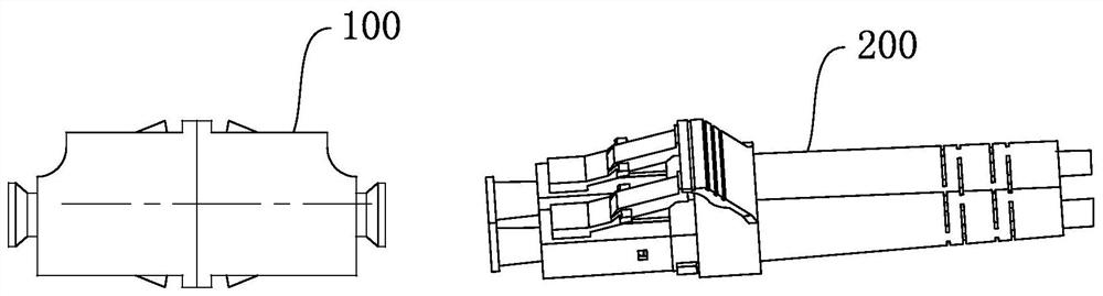
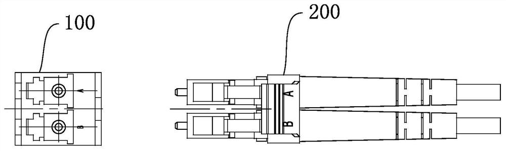
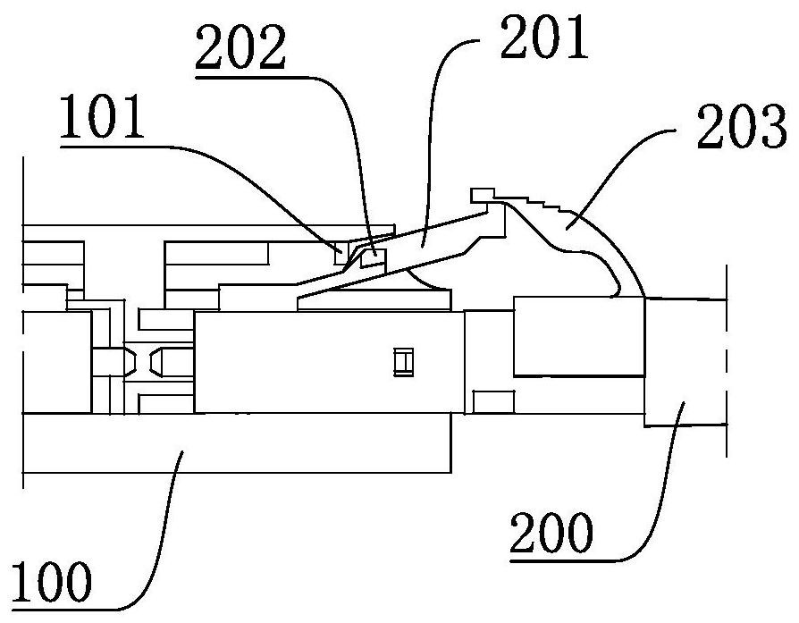
[0052] Such as Figure 4 to Figure 17 As shown, the connector assembly includes a plug 1 and an adapter 2 mated with the plug 1, with the plug-in end of the plug 1 as its front end, the plug-in and pull-out direction of the plug is the front-to-back direction, and the plug-in end of the adapter 2 as the front end of the adapter. The front end takes the height direction of the plug as the up and down direction. In this embodiment, the plug 1 is an optical fiber plug connector, and the plug 1 includes a plug housing 11 and an optical fiber ferrule 12 installed in the plug housing.

[0053] The upper part of the front end of the plug housing 11 is provided with a convex key 111, and the upper part of the mating end of the adapter 2 is provided with a locking claw 21. The locking claw 21 is an elastic arm type structure, and its rear end is a fixed end, and the front end is a movable end. The protruding key 111 and the locking pawl 21 are snap-locked to realize the independent loc...


PUM


Abstract

The invention relates to a connector assembly and a plug and an adapter thereof. The connector assembly comprises the plug and the adapter; the plug comprises a plug shell; the plug end of the plug shell serves as the front end, the height direction of the plug serves as the vertical direction, and the upper portion of the front end of the plug shell is provided with a protruding key and a locking groove located behind the protruding key; a locking claw is arranged at the upper part of the plug end of the adapter, falls into the locking groove and is matched with the protruding key in a stopping manner, so that the plug and the adapter are locked; and the plug shell is movably provided with a stopper along the plugging direction, and the stopper limits the upward lifting of the locking claw during locking, thereby preventing the unlocking of the plug and the adapter. According to the connector assembly, independent locking and unlocking of the plug can be completed, and the operation space needed in the longitudinal direction during unlocking is reduced; and the locking mechanisms are located in the upper spaces of the plug two ends, so that the spaces on the two sides of the connector are saved, the transverse width of the connector is reduced, the size of the connector is smaller, and transverse high-density deployment is facilitated.

Description

technical field [0001] The invention belongs to the technical field of connectors, in particular to a connector assembly, a plug and an adapter thereof. Background technique [0002] With the unprecedented increase in data demand for communication networks such as 5G and data centers, how to achieve higher speed and capacity transmission in a limited space is a problem that network equipment manufacturers continue to face. High-density deployment is the most direct solution. The size of connectors, adapters, and optical modules is reduced, the number of cores is increased, and more modules and connectors are deployed in a limited space. [0003] In current communication systems, LC or duplex LC fiber optic connectors are the most widely used (two LC connectors are used to fix them together). The existing structures of LC fiber optic connectors and adapters can be found in US5638474A and US5481634A content disclosed in . For example Figure 1 to Figure 2 , which is a schema...

Claims


Application Information

Patent Timeline
Patent Type & Authority Applications(China)
IPC IPC(8): G02B6/38H01R24/00H01R13/639H01R13/40
CPCG02B6/3825G02B6/387G02B6/3891H01R24/00H01R13/639H01R13/40Y02T10/70
Inventor 宋洋李平均谢庆陆田建伟孙亚磊
Owner CHINA AVIATION OPTICAL-ELECTRICAL TECH CO LTD
Why Eureka
Try Eureka