Vertical dewatering mop bucket for flat mop
A flat mop and mop bucket technology, applied in the field of mop buckets, can solve the problems of easy shaking, easily damaged wipes, unable to squeeze clean with water, etc., and achieve the effect of preventing shaking and improving dehydration quality.
- Summary
- Abstract
- Description
- Claims
- Application Information
AI Technical Summary
Problems solved by technology
Method used
Image

Examples
Embodiment 1
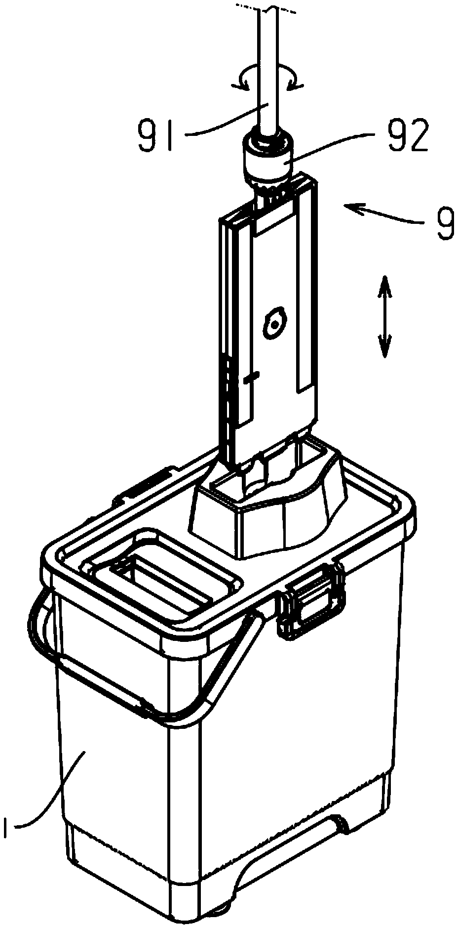
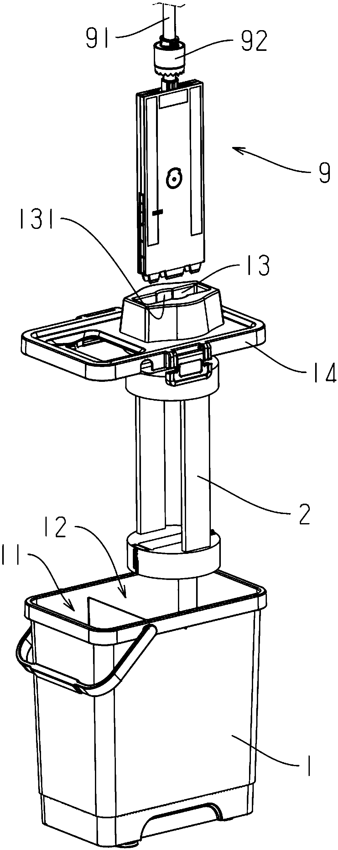
[0068] Embodiment 1: a flat mop vertical dehydration mop barrel, the flat mop 9 has a rotating mop bar, the mop head of the flat mop can be driven to rotate by pressing down on the mop bar, as Figure 1 to Figure 3 Shown: comprise mop bucket 1, described mop bucket has cleaning zone 11 for described flat mop cleaning and dehydration zone 12 for described flat mop dehydration, and described dehydration zone is provided with dehydration frame 2, and described dehydration frame Rotationally connected to the mop bucket, the dehydration rack can rotate around its longitudinal axis, and is provided with a locking mechanism 3 capable of restricting its rotation;
[0069] The cleaning area is provided with a cleaning piece for cleaning the wipes of the flat mop, and the cleaning piece is at least one of a cleaning brush, a cleaning scraper (wiper strip), a cleaning scraper, and a cleaning roller. The cleaning roller includes two types of rotatable and non-rotatable.
[0070] During d...
Embodiment 2
[0093] Embodiment 2: the difference with embodiment is:
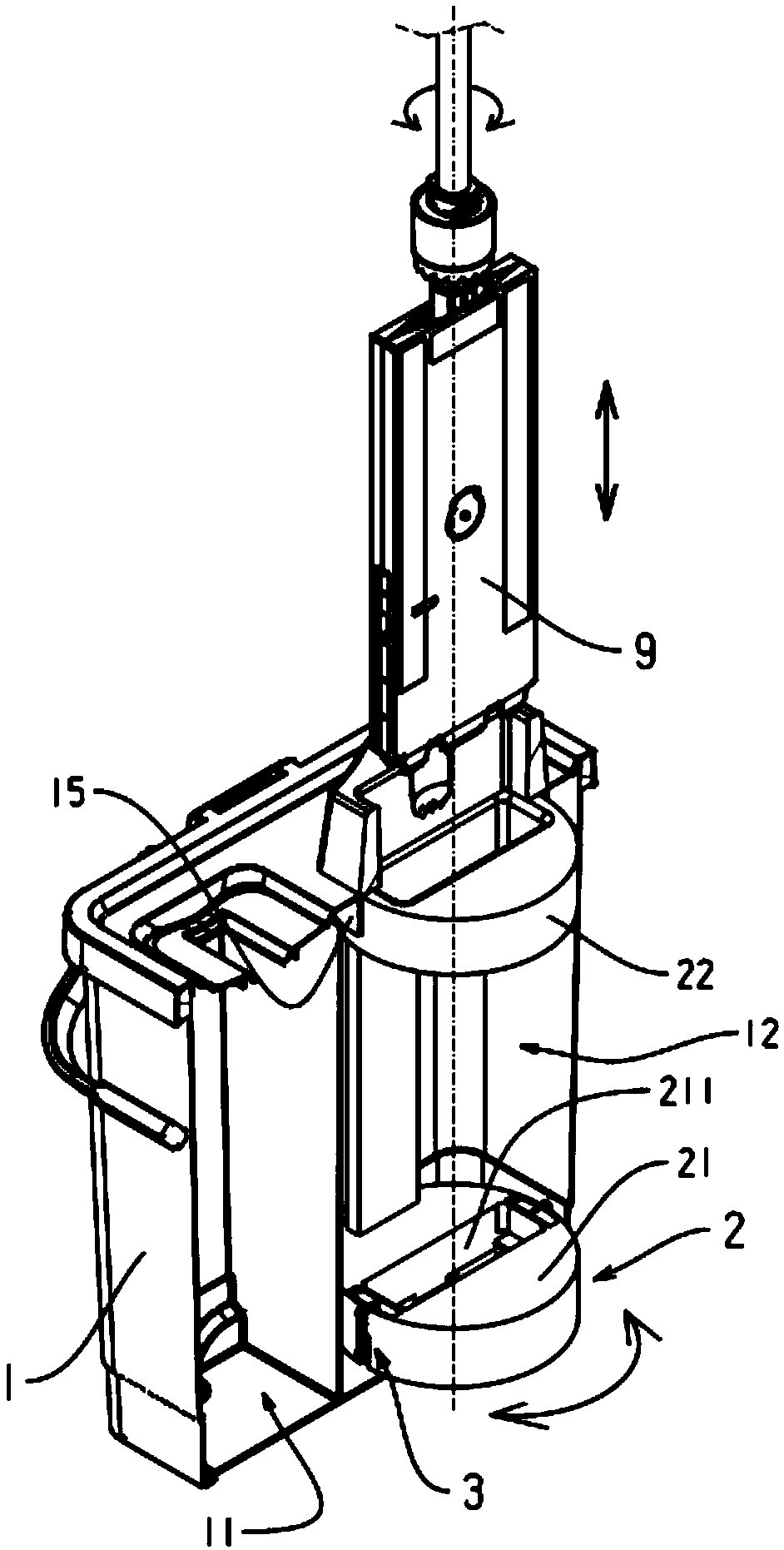
[0094] Such as Figure 13 to Figure 16 As shown: the dehydration rack is rotatably connected to the mop bucket, and the dehydration rack can move along its axial direction, and the locking mechanism includes a protrusion 321 located on the upper positioning plate 22 and a protrusion 321 located on the The groove 322 of the bung, or the locking mechanism includes a groove on the upper positioning plate and a protrusion on the bung, and the dehydration frame can move along its axial direction and is formed with high positions and Low position, the high position is close to the bucket cover, and the low position is close to the bottom of the bucket. In the initial state (locked state), the dehydration frame moves towards the bucket cover, and the grooves and protrusions are engaged with each other, thereby limiting The rotation of the dehydration rack, the flat mop is inserted into the dehydration rack and pressed down, s...
Embodiment 3
[0099] Embodiment 3: the difference with embodiment 1 is:
[0100] Such as Figure 17 to Figure 19 As shown: the locking mechanism includes a swing lock 331 arranged on the upper positioning plate 22 , the middle part of the swing lock is rotatably connected to the upper positioning plate, and the swing lock is located at the through opening 221 One end 3311 of the swing lock can protrude from the side wall of the upper positioning plate, and the other end 3312 can protrude to the through opening, and the side wall of the limit ring 15 has a One end 3311 of the swing lock catch falls into the positioning groove 332, and one end 3311 of the swing lock catch protrudes from the upper end of the upper positioning plate and falls into the positioning groove 332, thereby locking the upper positioning plate, and then restricting the rotation of the dehydration frame;
[0101] The swing lock is provided with a reset member 313, and the reset member is an elastic member (such as vari...
PUM
 Abstract
Description
Claims
Application Information
 - R&D Engineer
- R&D Manager
- IP Professional
- Industry Leading Data Capabilities
- Powerful AI technology
- Patent DNA Extraction
Browse by: Latest US Patents, China's latest patents, Technical Efficacy Thesaurus, Application Domain, Technology Topic.
© 2024 PatSnap. All rights reserved.Legal|Privacy policy|Modern Slavery Act Transparency Statement|Sitemap