Rotary separation device for sludge treatment

A technology of rotary separation and sludge, applied in the fields of sludge treatment, water/sludge/sewage treatment, separation methods, etc., can solve the problems of high water content of sludge, troublesome, poor separation effect of sludge and water, etc. Achieve the effect of improving dewatering quality, reducing parts cost and improving sludge treatment effect

Active Publication Date: 2022-06-24
海普欧环保集团有限公司
View PDF6 Cites 0 Cited by
  • Summary
  • Abstract
  • Description
  • Claims
  • Application Information

AI Technical Summary

Problems solved by technology

[0003] However, in the centrifugal concentration process of the existing sludge thickening device, due to the different particle sizes of the sludge, the separation effect of the sludge and water will be poor, and the water content in the concentrated sludge is high, so it needs to be dried again Dry, more troublesome, therefore, need further improvement

Method used


Image

  • Rotary separation device for sludge treatment
  • Rotary separation device for sludge treatment
  • Rotary separation device for sludge treatment

Examples


Embodiment 1

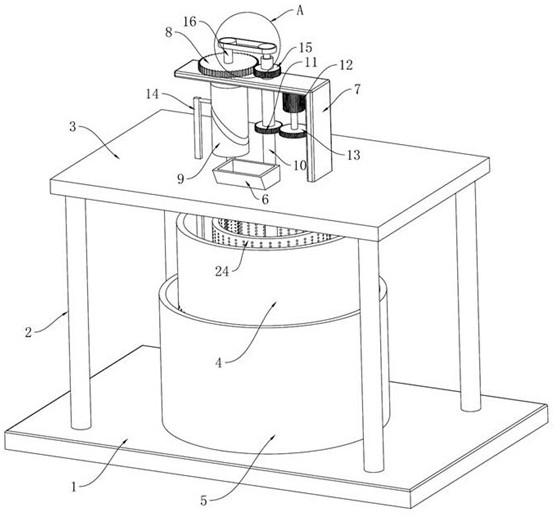
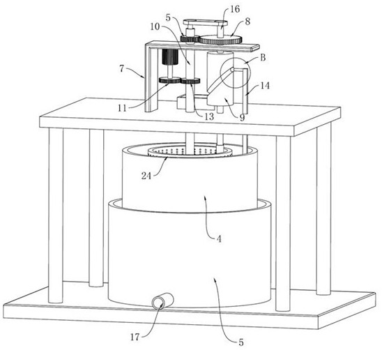
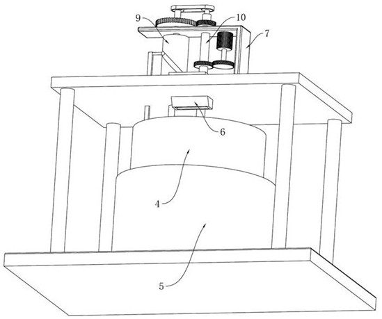
[0035] see Figures 1 to 8 , In the embodiment of the present invention, a rotary separation device for sludge treatment includes a fixed base 1, and the four corners of the upper end of the fixed base 1 are connected with a top plate 3 through a fixed column 2, and a support frame 7 is fixedly installed on the top plate 3. The support frame 7 and the top plate The outer shaft 10 is rotated and connected between 3, the bottom of the outer shaft 10 is installed through the top plate 3 to install the inner centrifugal bucket 24, the top of the outer shaft 10 is connected to the driving gear 15 through the support frame 7, and the outer side of the driving gear 15 is meshed with a driven gear Gear 8, the driven gear 8 is axially fixed to install the rotating shaft 16, the lower end of the rotating shaft 16 is connected to the rotating roller 9 through the support frame 7, the bottom of the rotating shaft 16 is connected to the cleaning roller close to the inner wall of the inner c...

Embodiment 2

[0046] In another embodiment of the present invention, the difference between this embodiment and the above-mentioned embodiment is that the support frame 7 is an L-shaped structure, which not only realizes the effective rotation limit of the outer shaft 10 and the rotation shaft 16 , while avoiding the interference between the various components.

[0047] The working principle of the present invention is as follows: during operation, the sludge enters the inner centrifugal bucket 24 through the sewage inlet hopper 6, and then the driving motor 12 is started, and the driving motor 12 will make the inner centrifugal bucket 24 and the outer centrifugal bucket 4 rotate synchronously, The sludge is dewatered twice. After the sewage is stored in the dewatering bucket 5, it is discharged by the drain pipe 17. After the sewage is discharged, the sludge remains in the inner centrifugal bucket 24 and the outer centrifugal bucket 4. , and then open the switch valve, so that the sludge i...


PUM


Abstract

The invention relates to the technical field of sludge treatment equipment, and discloses a rotary separation device for sludge treatment, which includes a fixed base, and the four corners of the upper end of the fixed base are connected with a top plate through fixed columns, and a support frame is fixedly installed on the top plate, between the support frame and the top plate The outer shaft is connected through rotation; the outer shaft has a hollow structure inside, and an inner shaft is provided for the inner rotation. The top of the shaft passes through the top of the outer shaft and is connected to the rotating shaft through the pulley. A rotating groove is arranged on the outer side of the rotating roller, and a rotating ball is slidably arranged inside the rotating groove. The present invention realizes double separation and dehydration of sludge, and further improves the effect of sludge treatment; realizes the cleaning effect on the inner walls of two centrifugal buckets, avoids the centrifugation hole being blocked by sludge during the centrifugation process, and greatly improves the efficiency of sludge treatment. sludge dewatering quality.

Description

technical field [0001] The invention relates to the technical field of sludge treatment equipment, in particular to a rotary separation device for sludge treatment. Background technique [0002] With the continuous improvement of people's living standards, people's awareness of environmental protection is also continuously strengthened. Among them, the protection of water environment is mainly reflected in two aspects: prevention before water pollution, treatment after water pollution, and water pollution. The previous prevention is mainly to control the discharge of industrial sewage and domestic sewage. For the discharge of industrial sewage and domestic sewage, it is necessary to meet the discharge standards to ensure that the discharged sewage will not pollute the water environment. Sludge sewage is usually taken out of water sludge by means of sludge concentration, and in the case of a large amount of sludge in the water environment, the method of sludge concentration c...

Claims


Application Information

Patent Timeline
Patent Type & Authority Patents(China)
IPC IPC(8): C02F11/127B01D33/11B01D33/42B01D33/46
CPCC02F11/127B01D33/11B01D33/42B01D33/465B01D33/461
Inventor 颜炳林杨青管延富高朋
Owner 海普欧环保集团有限公司
Why Eureka
Try Eureka