

Chemical experiment tube placement rack
A technology for chemical experiments and placing racks, which is applied in the direction of test tube holders/clamps, laboratory utensils, chemical instruments and methods, etc. It can solve the problems of inability to adjust the inclination angle of test tubes and inconvenient search of test tubes, so as to facilitate maintenance operations and save experiments. Preparation time and the effect of reducing the consumption of stamina
- Summary
- Abstract
- Description
- Claims
- Application Information
AI Technical Summary
Problems solved by technology
Method used
Image

Examples
Embodiment 1
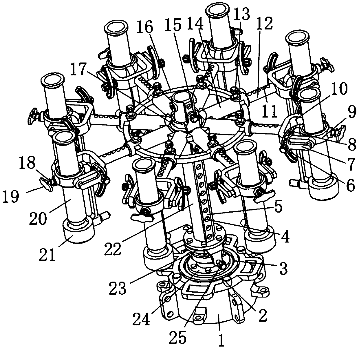
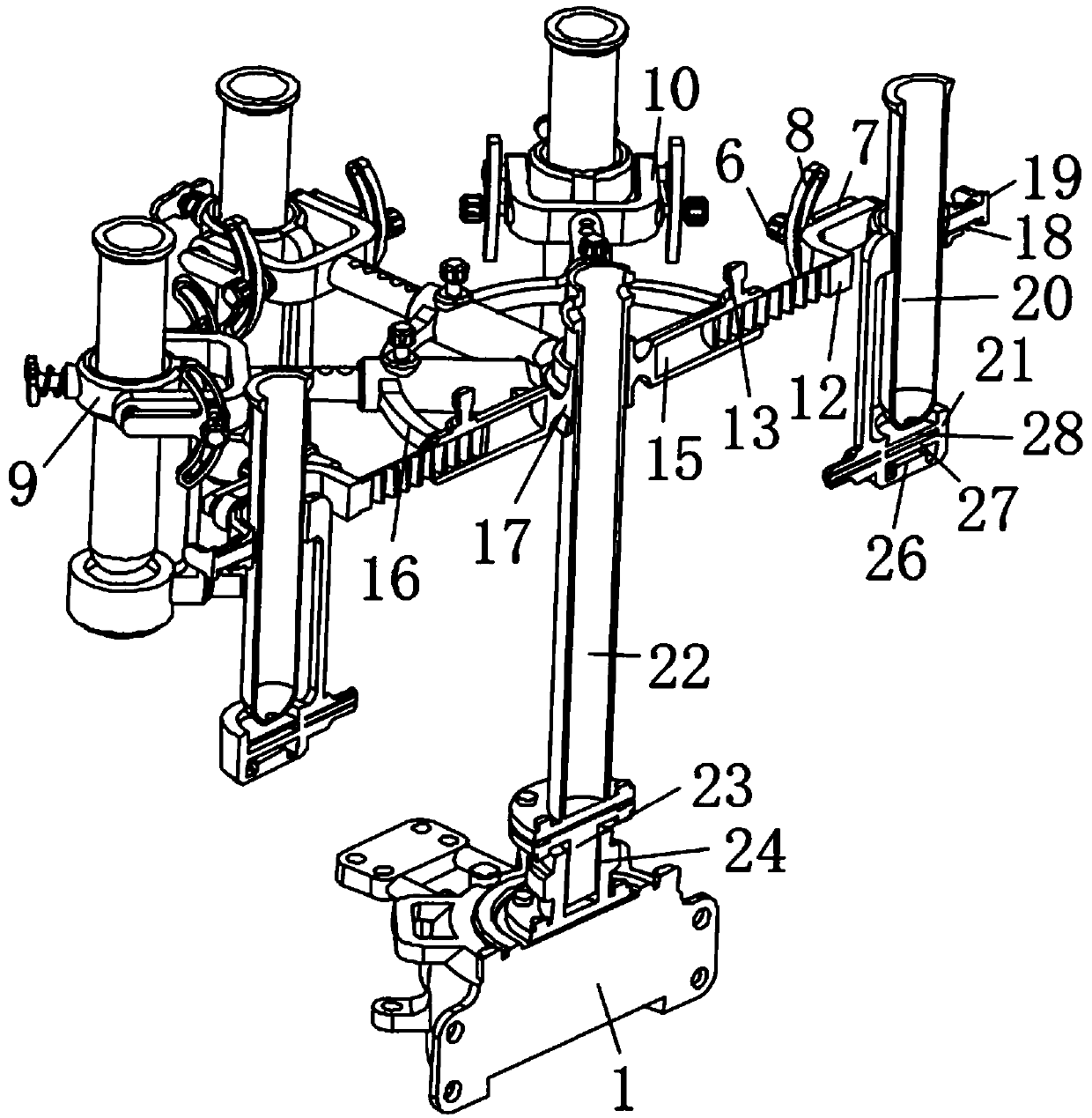
[0027] see Figure 1 to Figure 3 , the present invention provides a technical solution: a test tube placement rack for chemical experiments, including a base 1, a storage battery 3 is fixedly installed in the base 1 through bolts, and at least two independent batteries electrically connected to the storage battery 3 are fixedly installed on the base 1. Working button switch 2, the top of the base 1 is fixedly equipped with a lower mating seat 24 by bolts, and an upper mating seat 23 is installed above the lower mating seat 24 through a bearing, and the upper mating seat 23 is screwed and installed with a lower mating seat 24 Clamped matching seat positioning screw button 25;
[0028] The top of the upper mating seat 23 is fixed with a column 22 by bolts, and a guide protrusion 5 is integrally formed on the top of the column 22. The column 22 is sleeved with a sliding seat 17 that slides along the guide protrusion 5, and the sliding seat 17 At least four sleeves 14 are welded ...
Embodiment 2
[0035] see Figure 1 to Figure 4 , the present invention provides a technical solution: a test tube placement rack for chemical experiments, including a base 1, a storage battery 3 is fixedly installed in the base 1 through bolts, and at least two independent batteries electrically connected to the storage battery 3 are fixedly installed on the base 1. Working button switch 2, the top of the base 1 is fixedly equipped with a lower mating seat 24 by bolts, and an upper mating seat 23 is installed above the lower mating seat 24 through a bearing, and the upper mating seat 23 is screwed and installed with a lower mating seat 24 Clamped matching seat positioning screw button 25;
[0036] The top of the upper mating seat 23 is fixed with a column 22 by bolts, and a guide protrusion 5 is integrally formed on the top of the column 22. The column 22 is sleeved with a sliding seat 17 that slides along the guide protrusion 5, and the sliding seat 17 At least four sleeves 14 are welded ...
Embodiment 3
[0043] see figure 1 , figure 2 and Figure 5 , the present invention provides a technical solution: a test tube placement rack for chemical experiments, including a base 1, a storage battery 3 is fixedly installed in the base 1 through bolts, and at least two independent batteries electrically connected to the storage battery 3 are fixedly installed on the base 1. Working button switch 2, the top of the base 1 is fixedly equipped with a lower mating seat 24 by bolts, and an upper mating seat 23 is installed above the lower mating seat 24 through a bearing, and the upper mating seat 23 is screwed and installed with a lower mating seat 24 Clamped matching seat positioning screw button 25;
[0044] The top of the upper mating seat 23 is fixed with a column 22 by bolts, and a guide protrusion 5 is integrally formed on the top of the column 22. The column 22 is sleeved with a sliding seat 17 that slides along the guide protrusion 5, and the sliding seat 17 At least four sleeves...
PUM
| Property | Measurement | Unit |
|---|---|---|
| Length | aaaaa | aaaaa |
Abstract
Description
Claims
Application Information