
Feeding cavity device and sand making machine

A technology of feed chamber and sand making machine, which is applied in the field of construction machinery and can solve the problems of uncontrollable material volume of impeller components

Active Publication Date: 2019-04-16
ZOOMLION HEAVY IND CO LTD
View PDF6 Cites 1 Cited by
  • Summary
  • Abstract
  • Description
  • Claims
  • Application Information

AI Technical Summary

Problems solved by technology

[0004] The purpose of the present invention is to provide a feeding chamber device capable of adjusting and controlling the amount of material entering the impeller assembly in order to overcome the problem in the prior art that the amount of material entering the impeller assembly cannot be controlled

Method used


Image

  • Feeding cavity device and sand making machine
  • Feeding cavity device and sand making machine
  • Feeding cavity device and sand making machine

Examples


Embodiment Construction

[0025] Specific embodiments of the present invention will be described in detail below in conjunction with the accompanying drawings. It should be understood that the specific embodiments described here are only used to illustrate and explain the present invention, and are not intended to limit the present invention.

[0026] In the present invention, in the case of no contrary description, the used orientation words such as "up, down, left and right" usually refer to the up, down, left and right shown in the accompanying drawings; "inside and outside" Refers to the inside and outside of the outline of each part itself. The present invention will be described in detail below with reference to the drawings and in combination with embodiments.

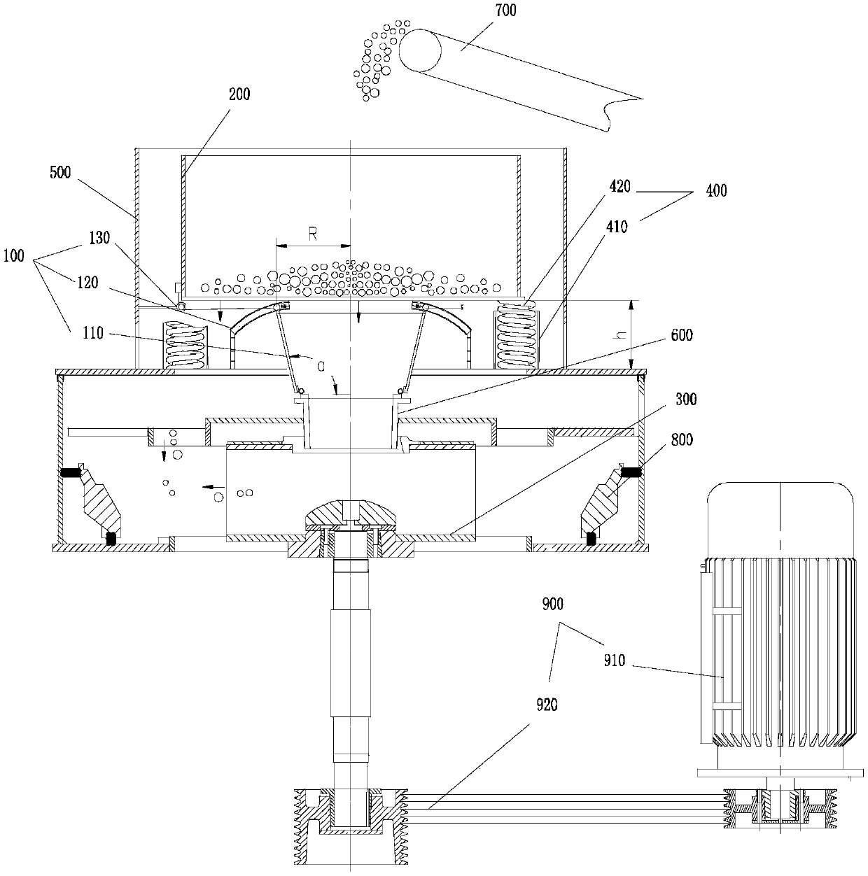
[0027] According to one aspect of the present invention, a feeding chamber device is provided, wherein the feeding chamber device 100 includes a feeding chamber main body 110, a guiding mechanism 120, and an adjusting mechanism 130, and...


PUM


Abstract

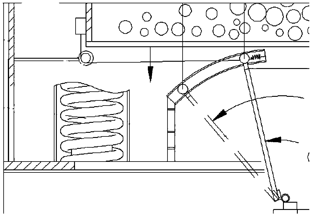
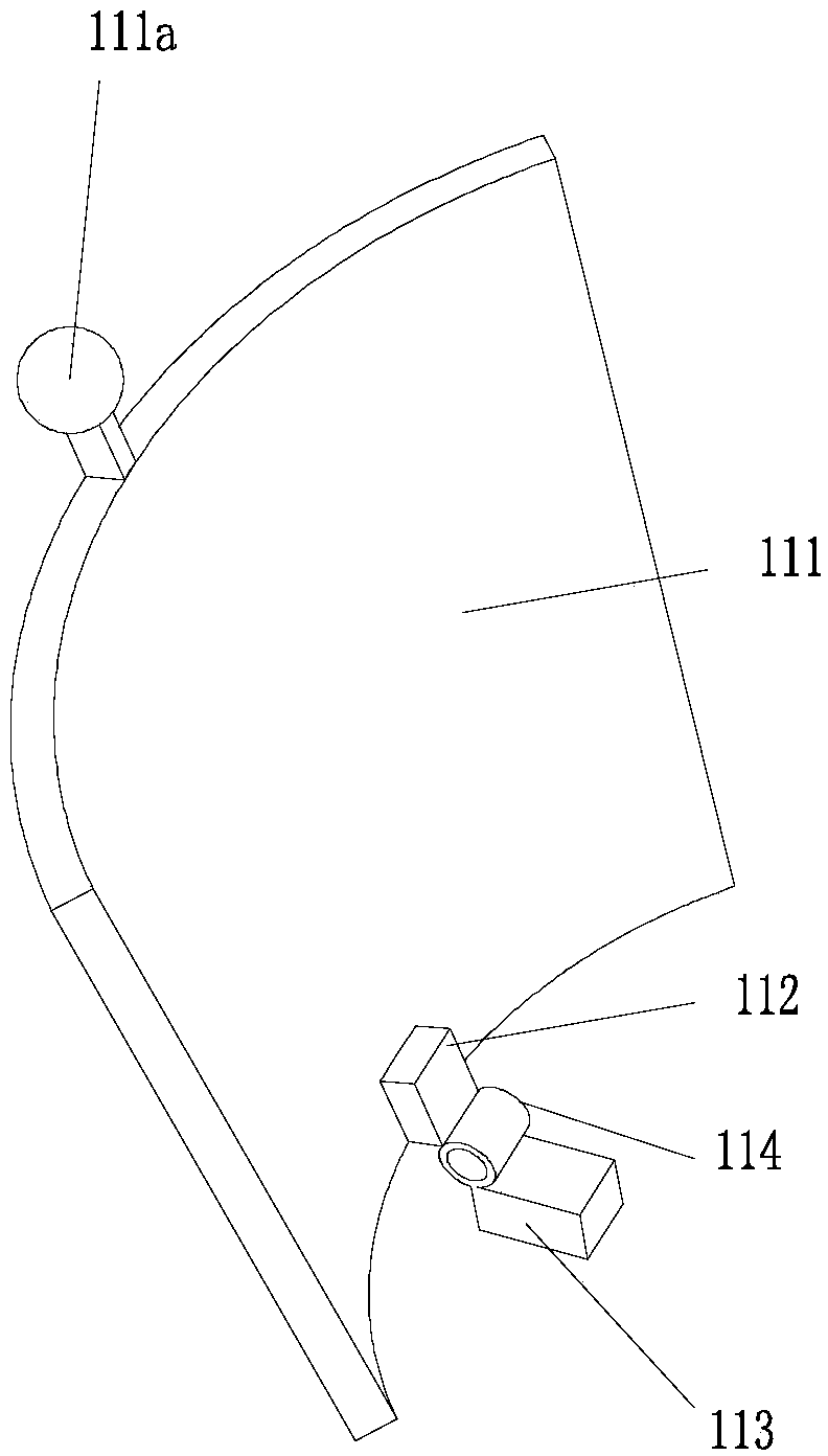
The invention relates to the field of engineering machinery, and discloses a feeding cavity device and a sand making machine. The feeding cavity device (100) comprises a feeding cavity main body (110), a guiding mechanism (120) and an adjusting mechanism (130), the guiding mechanism comprises a fixedly-arranged sliding way (121), the feeding cavity main body comprises multiple door plates (111) bywhich a cavity closed in the circumferential direction and opened in upper and lower ends can be defined, each door plate comprises a first end located at the lower end of the cavity and a second endlocated at the upper end of the cavity, each second end is provided with a sliding part (111a) driven by the adjusting mechanism, the first ends are arranged to enable the door plates to rotate relative to one another, therefore, the sliding parts are moved along the sliding way to change the size of the opening in the upper end of the cavity, and the size of the opening in the lower end of the cavity is kept unchanged. When the feeding cavity device is in use, the sliding parts are moved along the sliding way to change the size of the opening in the upper end of the cavity, and therefore theamount of materials fed by the feeding cavity device to an impeller assembly can be conveniently adjusted and controlled.

Description

technical field [0001] The invention relates to engineering machinery, in particular to a feeding chamber device and a sand making machine. Background technique [0002] Sand and gravel aggregate is the most widely used material in the field of construction. With the depletion of natural sand and gravel and the intensification of government environmental protection measures, natural sand resources are becoming increasingly depleted, and machine-made sand and gravel have become the mainstream of the sand and gravel aggregate industry. At present, sand and gravel can be prepared by a vertical shaft impact crusher, which mainly includes a feeding device, a hopper, an impeller assembly, a crushing chamber and other structures. The material is supplied from the feeding device to the hopper, and falls from the hopper into the impeller assembly and Kinetic energy is obtained through the rotation of the impeller assembly. When the material with certain kinetic energy moves outward f...

Claims


Application Information

Patent Timeline
Patent Type & Authority Applications(China)
IPC IPC(8): B02C19/00B02C23/02
CPCB02C19/0018B02C23/02
Inventor 钟进徐建华陈辉李远安
Owner ZOOMLION HEAVY IND CO LTD
Learn More