Platepaint spraying device for buildings

A technology for construction and boards, which is applied in the field of board processing, can solve the problems of high work intensity, low painting efficiency, and inability to realize double-sided painting, and achieve the effect of preventing paint waste

Inactive Publication Date: 2019-04-16
象山兑鹏电子科技有限公司
View PDF0 Cites 1 Cited by
  • Summary
  • Abstract
  • Description
  • Claims
  • Application Information

AI Technical Summary

Problems solved by technology

[0003] During the painting process of building boards, it is often necessary to spray paint on both sides of the boards. Most of the current painting methods are to spray paint on both sides of the boards with a spray gun manually. high
Although there are also automatic painting devices now, compared with the manual painting method, the efficiency of painting is improved and the work intensity is reduced, but double-sided painting cannot be realized. During the painting process, it is still necessary to manually flip and move the board, so that the spray head is different from the board. Paint is sprayed on the side or different parts, so the automatic painting device is now less automated

Method used


Image

  • Platepaint spraying device for buildings
  • Platepaint spraying device for buildings
  • Platepaint spraying device for buildings

Examples


Embodiment 1

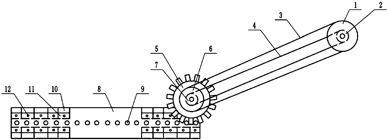
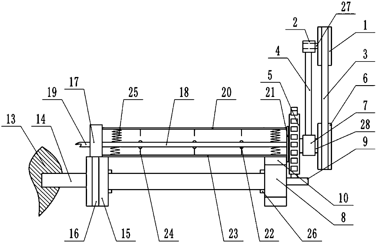
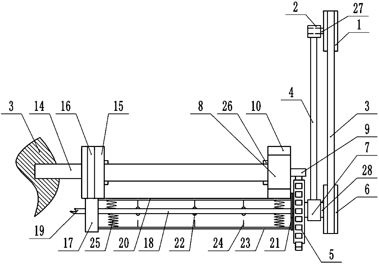
[0026] Embodiment 1 is basically as attached Figure 1-Figure 4 shown.

[0027] like figure 1 and figure 2As shown, the plate painting device for construction includes a frame, an active plate 8 and a driven plate 15 that are vertically arranged, the active plate 8 and the driven plate 15 are arranged oppositely, and the driven plate 15 is positioned at the rear of the active plate 8 . The top and the bottom of the active plate 8 are all provided with some movable blocks 10, the top and the bottom of the active plate 8 are all provided with some grooves 11, the movable blocks 10 are sealed and slidably connected in the groove 11, and the active plate 8 is provided with some The air inlet 12 communicated with the groove 11 is provided with an air valve, which can control whether the movable block 10 stretches out from the groove 11 by controlling whether to feed gas into the groove 11. A connecting plate is connected between the right end of the active plate 8 and the righ...

Embodiment 2

[0037] The difference between Embodiment 2 and Embodiment 1 lies in that the driving mechanism in Embodiment 2 is different from that in Embodiment 1. Embodiment 2 does not contain the first pulley 1, the second pulley 6 and the belt 3 in Embodiment 1. The driving mechanism in the second embodiment includes a motor slot arranged on the frame, and a motor is slidably connected in the motor slot, and the output shaft of the motor is directly coaxially connected with the gear 5 . The motor directly drives the gear 5 to rotate like this, and when the gear 5 swings, the motor slides in the motor groove following the swing of the gear 5, thereby adapting to the swing of the gear 5.


PUM


Abstract

The invention relates to the field of plate processing, in particular to a platepaint spraying device for buildings. The platepaint spraying device comprises a machine frame, a driving plate and a driven plate, wherein the driven plate is slidably connected to the machineframe; clamping pieces are correspondingly arranged on the driving plate and the driven plate; a plurality of meshing columns are fixedly arranged on the side surface of the driving plate;the meshing columns mesh with a gear, the driven plate is slidingly connected with a sliding block, a paint spraying pipe is connected between the sliding block and the gear, a plurality of spray holes are formed in the paint spraying pipe, pressure valves are arranged on the spray holes, a fixing plate is fixedly connected to the paint spraying pipe, an upper compression bar and a lower compression bar are slidably connected to the fixing plate, pressing needles are correspondingly arranged on the upper compression bar and the lowercompression bar, and compression springs arecorrespondingly connected between the paint spraying pipe and the upper compression bar andbetween the paint spraying pipe and the lower compression bar; and the machine frame is rotatably connected with a first shaft sleeve, the gear is rotatably connected with a second shaft sleeve, a connecting rod is connected between the first shaft sleeve and the second shaft sleeve, and a torsion spring is connected between the first shaft sleeve and the machine frame. According to the scheme, the two sides of a plate are automatically painted, and thepaint spraying automation degree is improved.

Description

technical field [0001] The invention relates to the field of plate processing, in particular to a paint spraying device for building plates. Background technique [0002] Building boards usually include solid wood boards, bamboo plywood, plywood, density boards, particle boards, three-layer boards and block boards. During the processing of building panels, it is often necessary to spray paint. On the one hand, the aesthetic effect of the panels can be improved by spraying paint. On the other hand, spraying paint can prevent external corrosion and play a certain protective role. [0003] During the painting process of building boards, it is often necessary to spray paint on both sides of the boards. Most of the current painting methods are to spray paint on both sides of the boards with a spray gun manually. high. Although there are also automatic painting devices now, compared with the manual painting method, the efficiency of painting is improved and the work intensity is...

Claims


Application Information

Patent Timeline
IPC IPC(8): B05B12/00B05B13/02
CPCB05B13/0221B05B12/00B05B13/0278
Inventor 肖锐
Owner 象山兑鹏电子科技有限公司
Why Eureka
Try Eureka