Deformation wheel with pulley and steel cable connection structure

A technology for connecting structures and steel cables, which is applied in the field of deformed wheels, can solve the problems of large ground damage, low safety, and easy slipping of the steel ring crawler, and achieves strong deformation recovery ability, improved shock absorption effect, and high deformation flexibility. Effect

Inactive Publication Date: 2019-04-16
定远县中林机械技术有限公司
View PDF1 Cites 4 Cited by
  • Summary
  • Abstract
  • Description
  • Claims
  • Application Information

AI Technical Summary

Problems solved by technology

[0005] Tracked wheels can adapt to various potholes and potholes, but their steel ring tracks do a lot of damage to the ground, and they are easy to slip when climbing stairs, so the safety is low; in view of this, patent CN 108403318 A proposes "a deformed wheel that can climb stairs." "Wheel", which adopts the hub structure in which the outer hub and the inner hub are slidingly connected by sliding pins through the chute, the outer hub is connected to the fixed spoke, and the inner hub is connected to the movable spoke, and the movable ends of the two rims are gathered when crossing obstacles or climbing stairs Or expand, so that the wheel adapts to the ups and downs of climbing stairs; but when it is under pressure, its spokes cannot shrink or elongate, and the compression of each spoke is inconsistent. After a hub overcomes obstacles, the spokes on it cannot recover quickly, resulting in The hub also cannot return to a round shape quickly, causing walking obstacles, and sometimes even requires manual assistance to restore

Method used


Image

  • Deformation wheel with pulley and steel cable connection structure
  • Deformation wheel with pulley and steel cable connection structure
  • Deformation wheel with pulley and steel cable connection structure

Examples


Embodiment Construction

[0027] The following will clearly and completely describe the technical solutions in the embodiments of the present invention with reference to the accompanying drawings in the embodiments of the present invention. Obviously, the described embodiments are only some, not all, embodiments of the present invention.

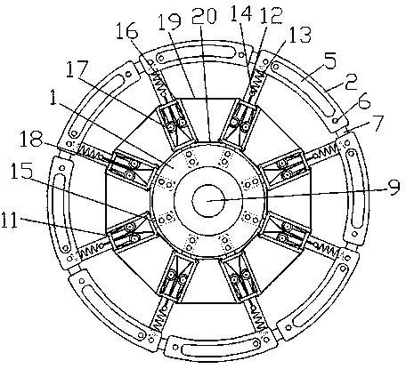
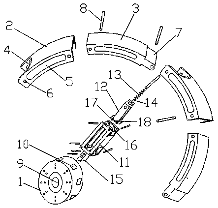
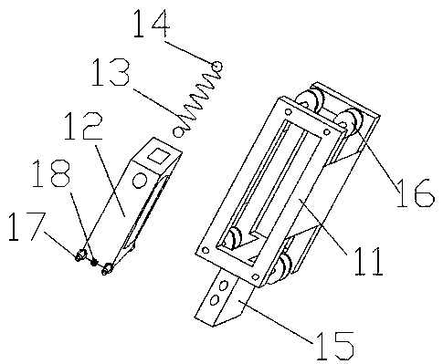
[0028] refer to Figure 1-5 , a deformed wheel with a pulley cable connection structure, mainly composed of a hub 1, a movable rim unit and a telescopic spoke unit, the movable rim unit includes an arc-shaped outer frame 2 and an arc-shaped inner frame 3, an arc-shaped outer frame 2 and an arc The cross section of shape inner frame 3 is door frame shape, and one end of arc outer frame 2 arc surface is provided with U-shaped notch 4, and the plane of arc outer frame 2 is provided with chute hole 5 and two pin holes 6, arc shape The inner frame 3 is socketed inside the arc-shaped outer frame 2, and the plane of the arc-shaped inner frame 3 is also provided with a chute...


PUM


Abstract

The invention discloses a deformation wheel with a pulley and steel cable connection structure, which mainly comprises a wheel hub, a moving wheel rim unit and a telescopic wheel spoke unit, wherein the moving wheel rim unit comprises an arc-shaped inner frame and an arc-shaped outer frame, the moving wheel rim unit forms a wheel rim structure through a serial connection mode of head to tail; thetelescopic spoke unit comprises a fixed frame, a sliding sleeve and a tension spring, wherein two ends of the tension spring are provided with circular rings, the tension spring is sleeved with the sliding sleeve, a rail wheel of the sliding sleeve is clamped on the inner frame of the fixed frame, one ends of the tension spring and sliding sleeve are clamped in the arc-shaped outer frame, the fixed frame is clamped in a clamping groove of the wheel hub through a clamping plate; four corners of the fixed frame are provided with four pulleys, two pulleys, the circular rings and the rail wheel are connected in series through an outer steel cable, and the other two pulleys are connected in series with a fixed point of the steel cable on the sliding sleeve by an inner steel cable. According tothe invention, the deformation wheel which is deformable in the circumferential direction and the radial direction is constructed, the deformation flexibility is high, the deformation recovery capability is strong, the deformation wheel can adapt to various landforms such as upstairs and downstairs, obstacle crossing and the like, and the deformation wheel is suitable for wide popularization and use.

Description

technical field [0001] The invention relates to the technical field of wheelchair wheels, in particular to a deformed wheel with a pulley cable connection structure. Background technique [0002] Ordinary wheelchairs do not have the functions of climbing stairs and cross-country obstacles, which greatly limits their scope of use. Therefore, technicians at home and abroad have proposed many special wheelchairs for climbing stairs and obstacles. There are many types of related devices and patents, mainly including crawler type, wheel group type and multi-legged type. Their functions and application characteristics are also different. There are pros and cons. [0003] For example, when a crawler wheelchair is turning, the steel ring crawler will cause great damage to the ground; when a multi-legged wheelchair is walking, each wheel (or supporting foot) will have a relatively uniform pull on the ground, but the seat will fluctuate and bump with the wheels (or supporting feet). ...

Claims


Application Information

Patent Timeline
Patent Type & Authority Applications(China)
IPC IPC(8): B60B19/00A61G5/06
CPCB60B19/00A61G5/061
Inventor 管中林
Owner 定远县中林机械技术有限公司
Why Eureka
Try Eureka