
Double lane chain filling and backstopping arrangement structure
An arrangement structure, chain technology, applied in fillings, safety devices, ground mining and other directions, can solve the problems of low efficiency and slow condensation, and achieve the effect of convenient use, accelerated solidification, and meet the needs of use
- Summary
- Abstract
- Description
- Claims
- Application Information
AI Technical Summary
Problems solved by technology
Method used
Image

Examples
Embodiment
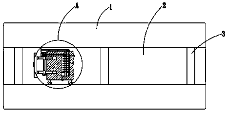
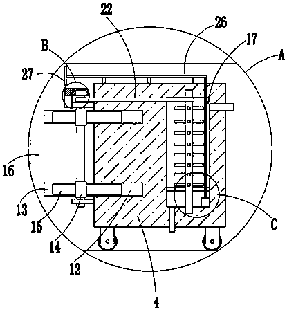
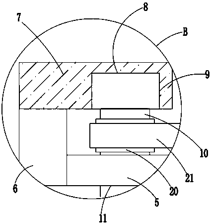
[0025] refer to Figure 1-5 , this embodiment proposes a double-lane chain filling mining layout structure, including a mining lane 1, a horizontal lane 2 is arranged on the mining lane 1, a coal pillar 3 is built in the horizontal lane 2, and a movable seat is arranged in the horizontal lane 2 4. Two side plates 5 are welded on one side of the moving seat 4, and a first plate 6 is welded on the side of the upper side plate 5 away from the moving seat 4, and a second plate 7 is welded on the top of the first plate 6. The bottom of the second plate 7 is provided with a mounting groove 8, and a rotating motor 9 is installed in the mounting groove 8. The output shaft of the rotating motor 9 is welded with a rotating shaft 10, and the top of the side plate 5 is provided with a rotating hole 11, and the rotating shaft 10 is rotated and installed. In the rotating hole 11, two slide grooves 12 are provided on one side of the moving seat 4, and a slide plate 13 is slidably installed i...
PUM
 Abstract
Description
Claims
Application Information