
Electromagnet for solenoid valve

A technology for electromagnets and solenoid valves, applied in the field of electromagnets for solenoid valves, can solve the problems of insufficient armature suction, magnetic field changes, and affecting the normal use of proportional electromagnets, so as to avoid changes in the magnetic field, stabilize the working magnetic field, and ensure normal use. Effect

Inactive Publication Date: 2019-04-16
HENAN PINGGAO ELECTRIC +2
View PDF7 Cites 6 Cited by
  • Summary
  • Abstract
  • Description
  • Claims
  • Application Information

AI Technical Summary

Problems solved by technology

[0006] However, because the outer cover of the above-mentioned proportional electromagnet can be taken out axially along both ends of the armature assembly, for the electromagnet as a whole, the axial relative position of the outer cover and the armature is not fixed, and relative displacement is likely to occur, which will cause the magnetic field generated by the coil to occur. Changes, changes in the magnetic field are likely to cause insufficient suction to the armature, which in turn affects the normal use of the proportional electromagnet

Method used


Image

  • Electromagnet for solenoid valve
  • Electromagnet for solenoid valve
  • Electromagnet for solenoid valve

Examples


Embodiment Construction

[0024] The specific embodiments of the present invention will be further described below in conjunction with the accompanying drawings.

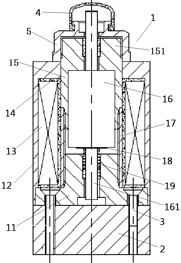
[0025] Such as Figure 2-Figure 5 As shown, Embodiment 1 of the solenoid valve electromagnet according to the present invention includes an armature assembly and a coil assembly. The coil assembly is sleeved on the armature assembly and fastened to the armature assembly by a nut 5. The nut 5 constitutes a fastening pieces.

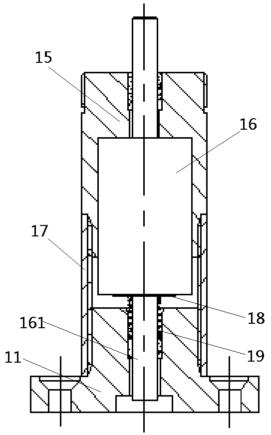
[0026] Such as figure 2 and image 3 As shown, the armature assembly includes an iron core base 11 , an inner static iron core 15 , a non-magnetic connection sleeve 17 connecting the inner static iron core 15 and the iron core base 11 , and an armature 16 that moves under the control of the magnetic field generated by the coil 13 .

[0027] Such as Figure 2-Figure 4 As shown, the iron core base 11 is a stepped shaft with a small top and a large bottom, including a chassis 111 and a cylindrical armature seat 112 int...


PUM


Abstract

The invention relates to an electromagnet for a solenoid valve. The electromagnet for the solenoid valve comprises an armature assembly and a coil assembly which sleeves the armature assembly, the armature assembly comprises an iron core base, an internal static iron core and an armature, and a non-magnetic conducting component is arranged between the iron core base and the internal static iron core in a separating mode. A top rod is arranged on the armature, and a through hole for the top rod to penetrate through downward is formed in the iron core base. The coil assembly comprises a coil andan external static iron core, an installation cavity for mounting into the coil is formed in the external static iron core, and a blocking and stopping part capable of preventing the coil from movingup is arranged on the installation cavity. The iron core base comprises a chassis and an armature seat, the upper end surface of the chassis is matched at the lower end of the coil in a supporting mode, a blocking and stopping surface matched with the upper end surface of the chassis in a blocking and stopping mode is arranged on the lower part of the external static iron core, an upper end partpenetrating through the upper end of the external static iron core is arranged on the inner static iron core, and a fastener pressing the external static iron core sleeves the upper end part of the internal static iron core. The electromagnet ensures the convenient disassembly and assembly of the coil, and ensures the continuous stability of a magnetic field produced by the coil.

Description

technical field [0001] The invention relates to an electromagnet for an electromagnetic valve. Background technique [0002] Solenoid valve is an automatic basic component for controlling fluid. It is often used to adjust the direction, speed, flow and other parameters of fluid. Solenoid valve generally includes electromagnet and hydraulic valve. [0003] During the working process of the electromagnet, sometimes the coil will burn out due to the heating time of the coil for a long time, or the insulation performance of the coil will be damaged due to the humidity of the surrounding air. At this time, the coil of the electromagnet needs to be replaced in time to ensure the normal operation of the solenoid valve. . However, the coil of most electromagnets is integrated with the housing, so that the coil cannot be replaced and the entire electromagnet or even the entire solenoid valve needs to be replaced, which greatly increases the maintenance cost of the solenoid valve. ...

Claims


Application Information

Patent Timeline
Patent Type & Authority Applications(China)
IPC IPC(8): F16K31/06
CPCF16K31/0672
Inventor 顾根泉张朝辉王亚辉张全民李文华王晗郑晓春高翔
Owner HENAN PINGGAO ELECTRIC
Learn More