Supercharge Your Innovation With Domain-Expert AI Agents!

Composite lamp mould

A composite, lighting technology, applied in the direction of loss prevention measures for lighting devices, cooling/heating devices for lighting devices, lighting and heating equipment, etc. Difficulties and other problems to achieve the effect of preventing electric shock

Inactive Publication Date: 2019-04-16
程寿珍
View PDF0 Cites 2 Cited by
  • Summary
  • Abstract
  • Description
  • Claims
  • Application Information

AI Technical Summary

Problems solved by technology

In the traditional production process, the lamp holder of the lamp and the rectifier are soldered and connected through exposed wires, but this connection method is too cumbersome, and it is easy to fall off after long-term use, causing an open circuit
[0003] Another reason is that the design of the composite lamp mold is unreasonable
Because the tail of the traditional composite lamp mold is relatively large, in order to ensure the molding of the tail, the remaining material of the product is relatively large, which brings great difficulties to the cutting and grinding of the subsequent process.
In the case of existing equipment, the increase of the remaining material increases the cutting and grinding damage and the amount of grinding, which leads to low cutting and grinding efficiency and a decrease in product yield
The arrangement of the wires leading out from the inside of the compound lamp mold to the rectifier is not very reasonable, and there are often situations such as shaking and loose fixation.

Method used


Image

  • Composite lamp mould
  • Composite lamp mould
  • Composite lamp mould

Examples


Embodiment Construction

[0018] Embodiments of the present invention will be further described below in conjunction with the accompanying drawings.

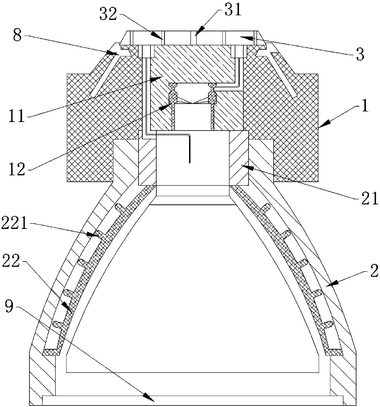
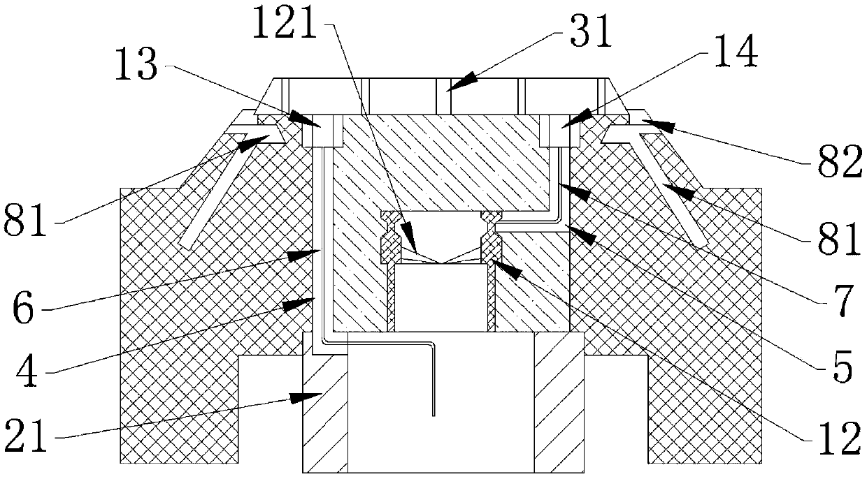
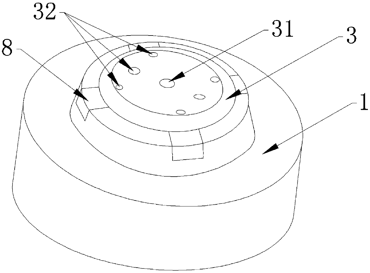
[0019] Such as Figure 1-3 As shown, this embodiment relates to a composite lamp mold, including an upper mold 1 and a lower mold 2 matched with the upper mold 1 . An abutment 11 is arranged inside the upper mold 1, and the abutment 11 is mainly used to lead out the connection wires of the lamps. The lower mold 2 is provided with a heat dissipation sleeve 22, and the heat dissipation sleeve 22 is connected with heat dissipation ribs 221. The arrangement of the heat dissipation sleeve 22 and the heat dissipation rib 221 can effectively diffuse the temperature of the lamp. The lower mold 2 is provided with a threaded mounting part 21 for fixing the lamp cap of the lamp. The threaded mounting part 21 can be effectively electrically connected with the threaded end of the lamp.

[0020] In this embodiment, the side wall of the threaded mounting part 21 is p...


PUM


Abstract

The invention discloses a composite lamp mould, which comprises an upper mould and a lower mould matched with the upper mould, wherein a base station is arranged in the upper mould; a heat dissipationsleeve is arranged outside the lower mould; a heat dissipation rib is connected outside the heat dissipation sleeve, wherein the lower mould is internally provided with a threaded mounting part for fixing a lamp holder of a lamp; the side wall of the threaded mounting part is axially extended and provided with a first wiring groove; the first wiring groove penetrates through the base station; thebase station is also internally provided with a supporting block; the supporting block is connected with a spring conductive sheet, the spring conductive sheet is connected to the tongue of the lamp,the supporting block is also connected with a second wiring slot, and the second wiring slot penetrates through the base station. According to the invention, the base station is arranged in the uppermold, and the first wiring groove and the second wiring groove are arranged on the base station, so that the lamp shell can conveniently connect lines at two ends of the lamp out.

Description

technical field [0001] The invention relates to the field of lighting appliances, in particular to a composite lamp mold. Background technique [0002] In the existing lighting industry, lamps and lanterns require composite lamp molds as connection terminals, and rectifiers are placed in the composite lamp molds to connect the lamps and external power lines through the rectifiers to achieve the purpose of taking electricity. In the traditional production process, the lamp holder of the lamp and the rectifier are connected by welding through exposed wires, but this connection method is too cumbersome, and it is easy to fall off after long-term use, causing an open circuit. [0003] Another reason is that the design of the composite lamp mold is unreasonable. Because the tail of the traditional composite lamp mold is relatively large, in order to ensure the shape of the tail, the remaining material of the product is relatively large, which brings great difficulties to the cut...

Claims


Application Information

Patent Timeline
IPC IPC(8): F21S8/00F21V15/015F21V17/12F21V17/16F21V23/06F21V25/00F21V27/00F21V29/83
CPCF21S8/00F21V15/015F21V17/12F21V17/164F21V23/06F21V25/00F21V27/00F21V29/83
Inventor 程寿珍
Owner 程寿珍
Features
  • R&D
  • Intellectual Property
  • Life Sciences
  • Materials
  • Tech Scout
  • Unparalleled Data Quality
  • Higher Quality Content
  • 60% Fewer Hallucinations
Learn More