Wig drying device

A drying device and wig technology, applied in wigs, heating devices, drying solid materials, etc., can solve the problems of low drying efficiency and high labor intensity, and achieve the effects of prolonging drying time, reducing labor intensity, and good heat preservation effect

Inactive Publication Date: 2019-04-16
禹州市金博发制品有限公司
View PDF6 Cites 3 Cited by
  • Summary
  • Abstract
  • Description
  • Claims
  • Application Information

AI Technical Summary

Problems solved by technology

[0002] There is a link in the wig making process that needs to straighten out the wig, then put it into water at different temperatures for stretching and shaping, so that the hair reaches the expected thickness, and then the wig is dried in the drying equipment , the way that the existing drying equipment generally adopts is to use a tray with several through holes to hold the wigs, place the tray in the drying equipment for drying, take out the tray after drying, and then put in another tray , the drying efficiency of this mode of operation is low, and it is necessary to manually carry the tray and put the tray in the drying equipment, and the labor intensity is also relatively large; Strong and efficient wig drying unit

Method used


Image

  • Wig drying device

Examples


Embodiment 1

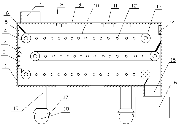
[0017] Such as figure 1 As shown, a wig drying device includes a box body 1, the box body 1 is a cuboid structure, the lower end of the box body 1 is fixedly connected with a leg 19, and the lower end of the leg 19 is rotatably connected There are rollers 18, and a belt conveying mechanism is arranged in the horizontal direction in the box body 1. There are three belt conveying mechanisms, and the conveying directions of two adjacent belt conveying mechanisms are opposite. The discharge end of the belt conveyor mechanism is located directly above the feed end of the belt conveyor mechanism on the lower floor adjacent to it. The belt conveyor mechanism includes a driving roller 4 and a driven roller 13, and the outside of the box body 1 A drive motor connected to the driving roller 4 is provided, and the driving roller 4 and the driven roller 13 are connected through a ring-shaped high-temperature-resistant mesh belt 10. The upper and lower half widths of the high-temperature-r...

Embodiment 2

[0020] Such as figure 1As shown, a wig drying device includes a box body 1, the box body 1 is a cuboid structure, the lower end of the box body 1 is fixedly connected with a leg 19, and the lower end of the leg 19 is rotatably connected There are rollers 18, and a belt conveying mechanism is arranged in the horizontal direction in the box body 1. There are three belt conveying mechanisms, and the conveying directions of two adjacent belt conveying mechanisms are opposite. The discharge end of the belt conveyor mechanism is located directly above the feed end of the belt conveyor mechanism on the lower floor adjacent to it. The belt conveyor mechanism includes a driving roller 4 and a driven roller 13, and the outside of the box body 1 A drive motor connected to the driving roller 4 is provided, and the driving roller 4 and the driven roller 13 are connected through a ring-shaped high-temperature-resistant mesh belt 10. The upper and lower half widths of the high-temperature-re...


PUM


Abstract

The invention relates to a wig drying device which comprises a box. Supporting legs are fixedly connected to the lower end of the box, belt type conveying mechanisms are arranged in the box, the discharging end of each belt type conveying mechanism is located over the feeding end of the adjacent lower-layer belt type conveying mechanism, each belt type conveying mechanism comprises a driving roller and a driven roller, the driving rollers and the driven rollers are in transmission connection through annular high-temperature-resistance meshed belts, electric heating pipes are arranged between the high-temperature-resistance meshed belts, LED heating lamps are arranged in the box, a support is arranged on the left side of the box, and an infrared heater is connected into the support. A temperature sensor and a humidity sensor are arranged in the box, a heat preservation layer is arranged on the inner wall of the box, humid discharging holes are formed in the top and the bottom of the box, a PLC is arranged on the outer wall of the box, and the temperature sensor, the humidity sensor, the LED heating lamps, the infrared heater and the PLC are all electrically connected. The wig dryingdevice has the advantages of being simple in structure, convenient to operate, complete in function, low in cost, high in practicability and high in efficiency.

Description

technical field [0001] The invention belongs to the technical field of wig products, and in particular relates to a wig drying device. Background technique [0002] There is a link in the wig making process that needs to straighten out the wig, then put it into water at different temperatures for stretching and shaping, so that the hair reaches the expected thickness, and then the wig is dried in the drying equipment , the way that the existing drying equipment generally adopts is to use a tray with several through holes to hold the wigs, place the tray in the drying equipment for drying, take out the tray after drying, and then put in another tray , the drying efficiency of this mode of operation is low, and it is necessary to manually carry the tray and put the tray in the drying equipment, and the labor intensity is also relatively large; Strong and efficient wig drying unit. Contents of the invention [0003] The object of the present invention is to overcome the def...

Claims


Application Information

Patent Timeline
Patent Type & Authority Applications(China)
IPC IPC(8): F26B15/18F26B3/30F26B23/06F26B25/00F26B25/02A41G3/00
CPCA41G3/0075F26B3/30F26B15/18F26B23/06F26B25/00F26B25/02
Inventor 张亚超
Owner 禹州市金博发制品有限公司
Why Eureka
Try Eureka