
Profile digital photography automatic measuring method

A technology of digital photogrammetry and digital photography, which is applied in the direction of measuring devices, instruments, and optical devices, can solve the problems of time-consuming and increasing data processing time, and achieve repeatability assurance of system measurement, reduce the number of shots, and improve The effect of system measurement accuracy

Active Publication Date: 2019-04-16
SHANGHAI INST OF SATELLITE EQUIP
View PDF7 Cites 9 Cited by
  • Summary
  • Abstract
  • Description
  • Claims
  • Application Information

AI Technical Summary

Problems solved by technology

[0004] During the thermal deformation test of large-scale antennas under normal pressure, the average time for each test is more than 20 days. On the one hand, it is due to the large number of test conditions, and on the other hand, it is due to the differences in the direction and flatness of each working condition. The measurement is very time-consuming, especially for large arrays; if there are 15 working conditions for each test, each working condition needs to be photographed at least three times. In addition, in order to ensure the validity of the measurement results, it is necessary to measure 2 to 3 times each time. The root mean square (RMS) of the repeatability error of 2 to 3 times is better than 0.03mm. The total number of effective measurements in each test needs to reach more than 150 times. In order to ensure that the repeatability of the measurement results meets the requirements, it is necessary to take hundreds of shots each time. At the same time, it also increases the post-data processing time; at the same time, because the measurement accuracy and measurement efficiency of digital photogrammetry are closely related to the human operation level

Method used


Image

  • Profile digital photography automatic measuring method
  • Profile digital photography automatic measuring method
  • Profile digital photography automatic measuring method

Examples


Embodiment Construction

[0047] The present invention will be described in detail below in conjunction with specific embodiments. The following examples will help those skilled in the art to further understand the present invention, but do not limit the present invention in any form. It should be pointed out that for those of ordinary skill in the art, several changes and improvements can be made without departing from the concept of the present invention. These all belong to the protection scope of the present invention. In the description of this application, it should be understood that the terms "upper", "lower", "front", "rear", "left", "right", "vertical", "horizontal", "top", The orientation or positional relationship indicated by "bottom", "inner", and "outer" is based on the orientation or positional relationship shown in the drawings, and is only for the convenience of describing the application and simplifying the description, and does not indicate or imply the device referred to Or the el...


PUM


Abstract

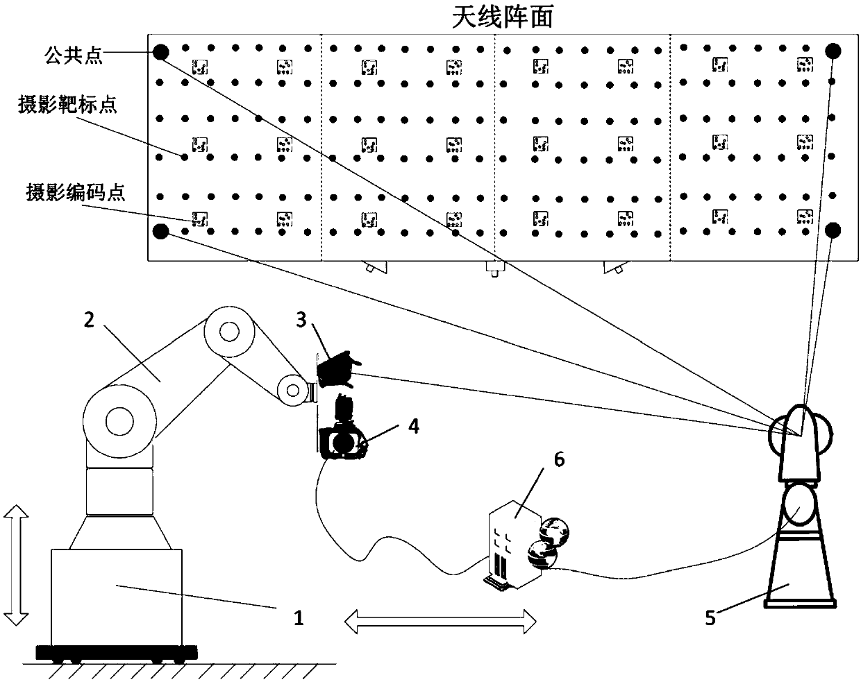
The invention provides a profile digital photography automatic measuring method. The profile digital photography automatic measuring method comprises the following steps that the position and the posture of the profile to be measured are measured by utilizing a laser tracker (5); the shooting position, angle and quantity of a digital photography measurement camera (4) is planned by utilizing a digital photography measurement principle; the mutual relation among an omni-directional movable lifting platform (1), a mechanical arm (2) zero position, a digital photography measurement camera (4), alaser tracker (5) and attitude measurement equipment (3) are marked in a laser tracker (5) coordinate system; the movement of the omni-directional movable lifting platform (1) and the mechanical arm (2) is controlled, so that the digital photography measurement camera (4) moving to a planned shooting position and angle; the profile is photographed, so that the orientation and the flatness of the profile can be obtained through a data acquisition and analysis system (6) processing. According to the profile digital photography automatic measuring method, high precision, high efficiency and automatic measurement can be carried out on the profile degree and the pointing precision of the large-scale antenna profile, and the profile digital photography automatic measuring method particularly aims at a process requiring multiple times of repeatability measurement.

Description

Technical field [0001] The invention relates to the technical field of industrial measurement, in particular to a profile digital photography automatic measurement method. Background technique [0002] As spacecraft have higher and higher requirements for the on-orbit performance of the antenna, the size of the antenna is getting larger and larger, and the requirements for profile accuracy, installation accuracy, reliability, and deformation indicators are getting higher and higher. In addition to the initial installation and deployment of the precise measurement of the antenna, more and more models require thermal deformation test verification on the ground. The atmospheric thermal deformation test needs to measure the changes in the orientation and flatness of the front surface. Common measuring equipment There are digital photogrammetry cameras, electronic theodolites, lidars, etc., according to different measurement requirements to select appropriate measurement equipment and...

Claims


Application Information

Patent Timeline
IPC IPC(8): G01B11/24
CPCG01B11/24
Inventor 李强车腊梅陈小弟刘四伟黄颖
Owner SHANGHAI INST OF SATELLITE EQUIP
Learn More