Guide rail splicing error measuring device
A technology of error measurement and measurement device, which is applied in the direction of measurement device, electric device, optical device, etc., can solve the problems of inability to detect side coplanar error, cumbersome and complicated measurement process, and inconvenient operation, so as to achieve convenient and efficient measurement and easy operation Simple, wear-free effect
- Summary
- Abstract
- Description
- Claims
- Application Information
AI Technical Summary
Problems solved by technology
Method used
Image
Examples
Embodiment 1
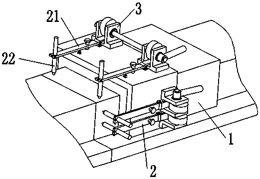
[0033] A kind of guide rail stitching error measurement device of this embodiment, such as figure 1 As shown, it includes an air flotation pallet 1, a measuring device 2, and a pressing mechanism 3. The top of the air flotation pallet 1 and an adjacent side at the top are respectively provided with a measuring device 2; the measuring device 2 includes a lever 21. Coplanarity sensor 22, the fulcrum of the lever 21 is installed on the side wall of the air floatation plate 1, the cantilever end of the lever 21 is provided with a coplanarity sensor 22, and the other end of the lever 21 is provided with a pressing Mechanism 3; the measuring device 2 includes two levers 21 arranged in parallel.
[0034] The air flotation pallet 1 is U-shaped and is slidably installed on the outside of the guide rail. The air bearing gap with the guide rail surface is between 5 μm and 10 μm. Using the air bearing plate 1 as the bearing and moving part can ensure that the whole device is almost in a ...
Embodiment 2
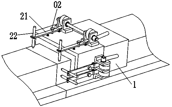
[0041] This embodiment is further optimized on the basis of embodiment 1, such as figure 2 As shown, a positioning screw 02 is also included, and the lever 21 is provided with a positioning screw 02 on a side close to the coplanarity sensor 22 of the fulcrum.
[0042] After the adjustment of the initial position of the coplanarity sensor 22 is completed, that is, after the initial position of the lever 21 is fixed, the initial position of the lever 21 should be kept unchanged during the subsequent measurement process. However, during the sliding process of the air bearing plate 1 and the frequent lifting and falling of the lever 21, the initial position of the lever 21 may change, and it is necessary to re-adjust the initial position at this time. In order to avoid the occurrence of the above situation, the initial position of the lever 21 is effectively maintained, so a set screw 02 is installed through the lever 21, and the initial position of the lever 21 is adjusted by tu...
Embodiment 3
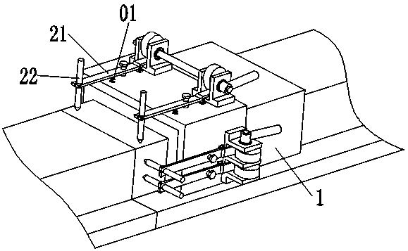
[0045] This embodiment is further optimized on the basis of above-mentioned embodiment 1 or 2, such as image 3 As shown, a measuring spring 01 is also included, and a measuring spring 01 is arranged between the lever 21 and the side wall of the air bearing plate 1 .
[0046] When measuring the flatness of the guide rail surface, the measuring end of the coplanarity sensor 22 should be in close contact with the guide rail surface, so a measuring spring 01 is arranged between the lever 21 and the guide rail surface, and when the lever 21 falls, the measuring spring 01 is in the In the slightly stretched state, the measuring spring 01 tightens the lever 21, so that the measuring end of the coplanarity sensor 22 is in close contact with the guide rail surface, and at the same time, the measurement repeatability of the coplanarity sensor 22 is ensured.
[0047] Other parts of this embodiment are the same as those of Embodiment 1 or 2 above, so details are not repeated here.
PUM
 Abstract
Description
Claims
Application Information
 - R&D
- Intellectual Property
- Life Sciences
- Materials
- Tech Scout
- Unparalleled Data Quality
- Higher Quality Content
- 60% Fewer Hallucinations
Browse by: Latest US Patents, China's latest patents, Technical Efficacy Thesaurus, Application Domain, Technology Topic, Popular Technical Reports.
© 2025 PatSnap. All rights reserved.Legal|Privacy policy|Modern Slavery Act Transparency Statement|Sitemap|About US| Contact US: help@patsnap.com


