A method for relative positioning of oblique camera based on deep learning

A technology of deep learning and relative positioning, applied in photogrammetry/video metrology, instruments, surveying and mapping and navigation, etc., can solve the problem that the positioning accuracy is greatly affected by the conversion accuracy, and achieve the effect of improving the relative positioning accuracy

Active Publication Date: 2021-01-01
甘肃大禹九洲空间信息科技有限公司
View PDF6 Cites 0 Cited by
  • Summary
  • Abstract
  • Description
  • Claims
  • Application Information

AI Technical Summary

Problems solved by technology

[0005] The purpose of the present invention is: the present invention provides a relative positioning method of oblique camera based on deep learning, which solves the problem that the positioning accuracy is greatly affected by the conversion accuracy in the existing method of using the essential matrix for conversion to obtain directional elements

Method used


Image

  • A method for relative positioning of oblique camera based on deep learning
  • A method for relative positioning of oblique camera based on deep learning
  • A method for relative positioning of oblique camera based on deep learning

Examples


Embodiment 1

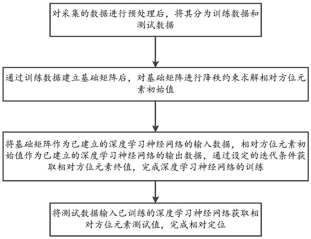
[0078] A method for relative positioning of oblique camera based on deep learning, comprising the steps of:

[0079] Step 1: After preprocessing the collected data, divide it into training data and test data;

[0080] Step 2: After the basic matrix is ​​established through the training data, the rank-reducing constraint is applied to the basic matrix to solve the initial value of the relative orientation element;

[0081] Step 3: Use the basic matrix as the input data of the established deep learning neural network, and the initial value of the relative orientation element as the output data of the established deep learning neural network, and obtain the final value of the relative orientation element through the set iteration conditions to complete the depth Learn the training of neural networks;

[0082] Step 4: Input the test data into the trained deep learning neural network to obtain the test value of the relative orientation element and complete the relative positioning...

Embodiment 2

[0085] Based on embodiment 1, step 1 includes the following steps:

[0086] Step 1.1: set a threshold, filter and delete the most value according to the threshold, and the most value includes the minimum value and the maximum value;

[0087] Step 1.2: Divide the data after removing the most value into training data and test data in proportion, and the ratio is 6:4 or 7:3.

[0088] Step 2 includes the following steps:

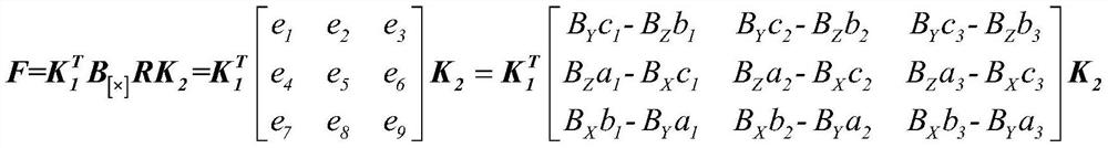
[0089] Step 2.1: Establish the basic matrix F according to the stereo pair in the training data. The stereo pair includes a left photo and a right photo, and the left photo and the right photo include a plurality of image points with the same name. The establishment equation is as follows:

[0090]

[0091] Among them, F represents the fundamental matrix between two images, B represents the photographic baseline vector, and B [×] Represents the cross-product matrix of vector B, m 1 , m 2 Indicates the image space auxiliary coordinates of the image point w...


PUM


Abstract

The invention, which relates to the field of tilted imaging relative positioning method, discloses a tilted shooting relative positioning method based on depth learning. The method comprise: step one,after preprocessing collected data, classifying the collected data into training data and test data; step two, establishing a basic matrix by the training data and carrying out reduced rank constraint on the basic matrix to calculate an initial value of a relative orientation element; step three, with the basic matrix as input data of the established deep learning neural network and the initial value of the relative orientation element as the output data, acquiring a final value of the relative orientation element based on a set iteration condition; and step four, inputting the test data intothe trained deep learning neural network to obtain a relative orientation element test value. Therefore, a defect that the positioning accuracy is greatly affected by the conversion accuracy in the method of obtaining the orientation element based on conversion with the essential matrix is overcome; the relative orientation element can be obtained precisely; and the relative positioning accuracyis improved.

Description

technical field [0001] The invention relates to the field of relative positioning methods for oblique photography, in particular to a relative positioning method for oblique photography based on deep learning. Background technique [0002] Oblique photography technology is a high-tech oblique photography developed in the field of international photogrammetry in the past ten years. This technology obtains rich images of building tops and side views by synchronously collecting images from one vertical angle of view and four oblique angles of view. High resolution textures. It can not only truly reflect the situation of ground objects, obtain object texture information with high precision, but also generate a real 3D city model through advanced positioning, fusion, modeling and other technologies. The relative orientation of oblique camera pairs is not only an important means to check the quality of image measurement, but also a necessary prerequisite for 3D reconstruction of ...

Claims


Application Information

Patent Timeline
Patent Type & Authority Patents(China)
IPC IPC(8): G01C11/00
CPCG01C11/00
Inventor 岳增琪贺伟
Owner 甘肃大禹九洲空间信息科技有限公司
Why Eureka
Try Eureka