Structured-light based measuring method and system

a technology of structured light and measuring method, applied in the field of structured light based measuring method and structured light based measuring system, can solve the problem of low measuring precision, achieve the effect of reducing the number of structures, simplifying the structure-light measuring process, and greatly improving the system measurement precision

Active Publication Date: 2016-06-07
SHENZHEN TAISHAN SPORTS TECH CO LTD
View PDF11 Cites 0 Cited by
  • Summary
  • Abstract
  • Description
  • Claims
  • Application Information

AI Technical Summary

Benefits of technology

[0019]In the inventive structured-light based measuring system, during the demarcating process by the demarcating module, a position of a laser output port relative the first camera is adjusted to prevent image positions of any two laser light spots within the first camera from overlapping with each other.
[0025]The structured-light based measuring method and a structured-light based measuring system using such a method of the present invention are advantageous in that the measurement precision of the system is greatly improved by adding the second camera for fine measurement to the existing structured-light measuring system.
[0026]In the invention, a demarcation database is established through the demarcating process, so that the structured-light measuring process is simplified. The image positions of any two laser light spots within the first camera do not overlap with each other, so that the accuracy of the mapping relationship between the image position and the depth of each laser light spot (that is formed on the measured object) within the first camera is ensured during the demarcating process. The distance between the second camera and the laser output port is larger than the distance between the first camera and the laser output port, so that a mapping relationship between the image position and the depth that is provided by the second camera is more precise than that provided by the first camera. A geometric region is used for surrounding image positions at various depths of the same laser light spot in order to conduct the demarcating process and the matching process, and the matching speed may be accelerated. During the calculating process, the precise position of the laser light spot is obtained by an interpolating method applied on the sequence of the image position in the second camera and the depth, so that multiple precise depths of the measured objected may be obtained. The matching is conducted according to the image position of the laser light spot within the first camera and the respective candidates of matching point within the second camera during the matching process, so that the matching result may be obtained more easily, simply and quickly.

Problems solved by technology

In an existing structured-light based measuring system, for the purpose of ensuring that the image distributions of any two light beams at different depths do not overlap with each other, it is necessary to concentrate the image distribution of each light beam, that is, a small image displacement corresponds to a large physical depth difference, which results in a low measuring precision.

Method used


Image

  • Structured-light based measuring method and system
  • Structured-light based measuring method and system
  • Structured-light based measuring method and system

Examples


Embodiment Construction

[0035]Preferred embodiments of the present invention are described in detail below in connection with the attached drawings.

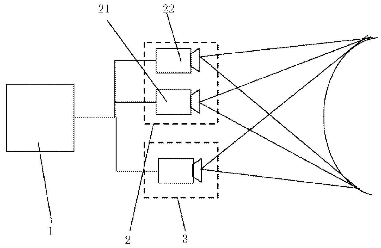
[0036]As shown in FIG. 1, a structured-light based measuring method of the invention includes a matching process and a calculating process, in which the used demarcation database is obtained through a demarcating process.

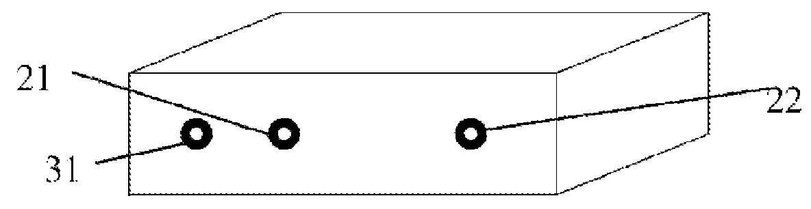
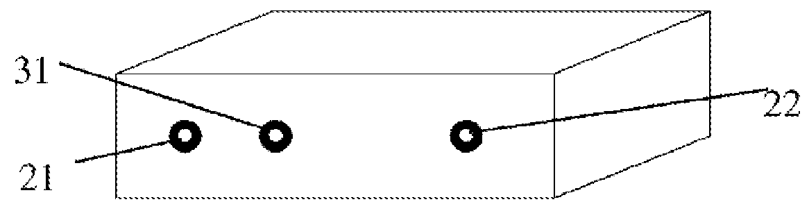
[0037]During the demarcating process, a first mapping relationship between an image position of each laser light spot within a first camera 21 and the sequence number as well as a low-precision depth (i.e. scene depth) of the laser light spot is determined. Particularly, in the case of the first camera 21, it is assumed that an image position of a laser light spot i at a depth within the first camera 21 is denoted by (uij, vij), and the image distributions of any two laser light spots are prevented from overlapping with each other by adjusting the position of the laser output port 31 (as shown in FIG. 6) with respect to the first camera 21, as ...


PUM


Abstract

A structured-light measuring method, includes: matching process, in which the number and the low-precision depth of a laser point are achieved by using the imaging position of the laser point on a first camera (21) according to a first corresponding relationship in a calibration database, and the imaging position of the laser point on a second camera (22) is searched according to the number and the low-precision depth of the laser point so as to acquire the candidate matching points, then the matching process is completed according to the imaging position of the first camera (21) and the candidate matching points of the imaging position of the first camera (21) on the second camera (22) so that a matching result is achieved; and computing process, in which the imaging position of the second camera (22) matching with the imaging position of the first camera (21) is achieved according to the matching result, and then the precision position of the laser point is determined by a second corresponding relationship in the calibration database. A structured-light measuring system utilizes the above measuring method.

Description

TECHNICAL FIELD[0001]The present application relates to a structured-light based measuring method and a structured-light based measuring system employing such a method, and particularly to a structured-light based measuring method and a structured-light based measuring system employing such a method with a high measurement precision.TECHNICAL BACKGROUND[0002]For a structured-light based measuring system, if a light beam spot and its corresponding coordinate Z are known, the coordinate of a cross point of the light beam on the surface of an object may be obtained. For this purpose, during the demarcation of the structured-light based measuring system, light beams of the structured-light are designed in such a way that the image distribution of a light beam of the structured-light does not overlap that of a neighboring beam of the structured-light within a camera, and the respective image positions are recorded for various depths (i.e. the coordinates Z). During the practical measurem...

Claims


Application Information

Patent Timeline
Patent Type & Authority Patents(United States)
IPC IPC(8): H04N7/18G06T7/00G01B11/25
CPCG01B11/2545G06T7/0057G06T2207/10012G06T7/521
Inventor SHI, DANWEIWU, DIZHAO, WENCHUANGXIE, QI
Owner SHENZHEN TAISHAN SPORTS TECH CO LTD
Why Eureka
Try Eureka