Waterproof and dustproof electric connector and pantograph charging connection structure

An electrical connector, waterproof and dustproof technology, applied in vehicle connectors, electric vehicle charging technology, connection and other directions, can solve the problems of poor waterproof and dustproof performance, poor waterproof and dustproof performance, hidden safety hazards, etc. Good ability, improve waterproof and dustproof ability, and ensure the effect of safety

Inactive Publication Date: 2019-04-16
JIANGSU WANBANG DEHE NEW ENERGY TECH CO LTD
View PDF6 Cites 2 Cited by
  • Summary
  • Abstract
  • Description
  • Claims
  • Application Information

AI Technical Summary

Problems solved by technology

[0006] The purpose of the present invention is to overcome the existing technology that the electrical contact surface of the fixed-end electrical connector is often exposed outside the environment, has poor waterproof and dustproof performance, and has potential safety hazards; and when the fixed-end electrical connector and the free-end electrical connector are connected and charged , some electrical connectors used as assemblies still have part or even all of the electrical contact surfaces exposed, poor waterproof and dustproof capabilities, and extremely poor security. A waterproof and dustproof tank body used as a fixed-end electrical connector is provided. Good ability and good safety; the second terminal and the first terminal are always electrically connected in the airtight notch, without contact with the external environment. When the electrical connector is in the charging state, it is also waterproof and dustproof, which is safe. Good waterproof and dustproof electrical connector and charging bow charging connection structure

Method used


Image

  • Waterproof and dustproof electric connector and pantograph charging connection structure
  • Waterproof and dustproof electric connector and pantograph charging connection structure
  • Waterproof and dustproof electric connector and pantograph charging connection structure

Examples


Embodiment Construction

[0062] The present invention is described in further detail now in conjunction with accompanying drawing. These drawings are all simplified schematic diagrams, which only illustrate the basic structure of the present invention in a schematic manner, so they only show the configurations related to the present invention.

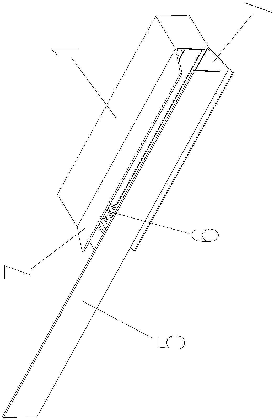
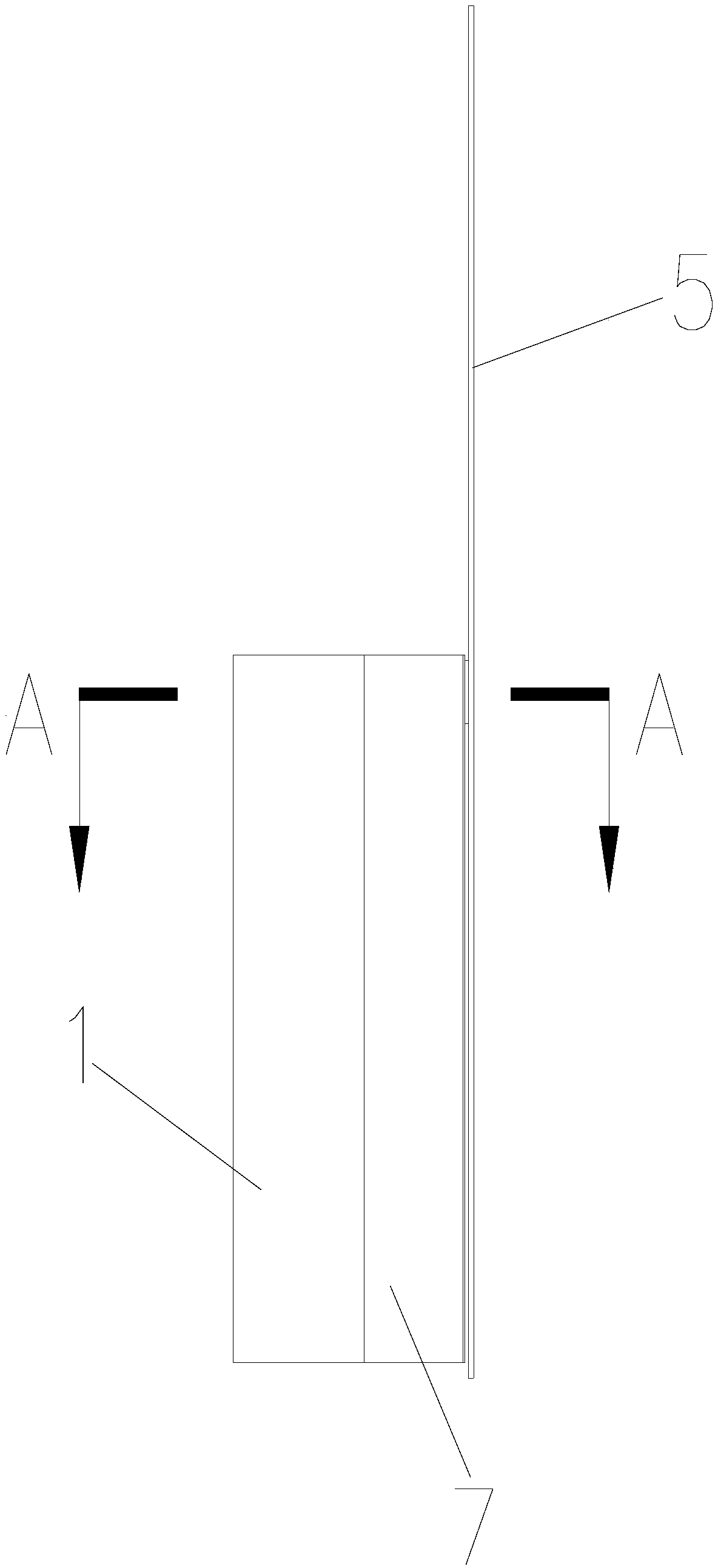
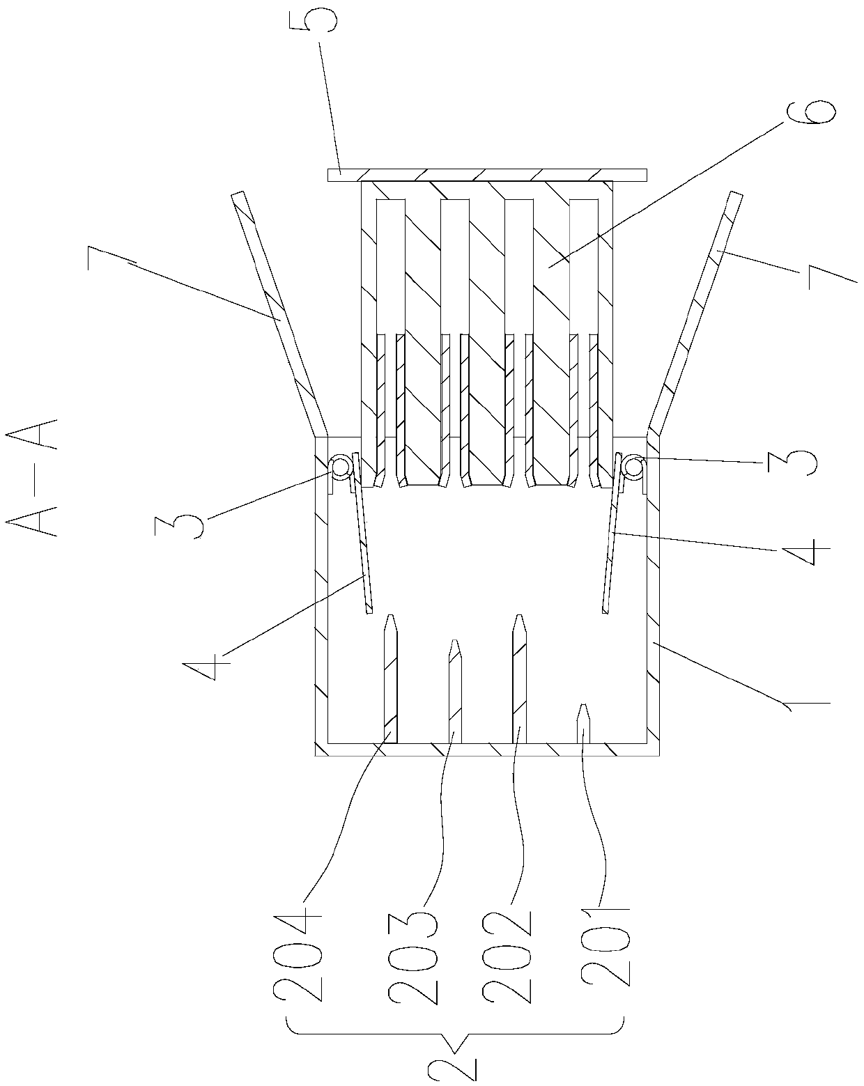
[0063] Such as Figure 1-Figure 3 The shown specific embodiment of a waterproof and dustproof electrical connector of the present invention includes a box-shaped tank body 1 and a movable plate 5, the first terminal 2 is installed in the tank body 1, and at least One inner surface is equipped with door panels 4 through the automatic door closing mechanism 3. When each door panel 4 is at a limit position, the notch of the tank body 1 is closed by each door panel 4; when each door panel 4 is at another limit position, each door panel 4 is in the groove The mouth is turned inward to the side of the inner side of the tank body 1; the second terminal 6 is installe...


PUM


Abstract

The invention belongs to the technical field of electric connectors and particularly relates to a waterproof and dustproof electric connector and a pantograph charging connection structure, comprisinga box-shaped tank body and a movable plate, wherein the tank body is provided therein with a first binding post; at least on inner side surface of the tank body is equipped with a door panel throughan automatic door closing mechanism; when each door panel is at an extreme position, the notch of the tank body is closed by each door panel; when each door panel is at another extreme position, eachdoor panel is inwards turned towards the notch to a side of the inner side surface of the tank body; a second binding post is mounted on the movable plate; and the movable plate closes the notch whenthe second binding post is inserted into the notch and electrically connected to the first binding post. The waterproof and dustproof electric connector has the beneficial effects that the tank body as a fixed-end electric connector has a good waterproof and dustproof capability and good safety; the second binding post and the first binding post are always electrically connected in the closed notch and are not in contact with the external environment; the electric connector is also waterproof and dustproof when in a charging state so as to achieve good safety.

Description

technical field [0001] The invention belongs to the technical field of electrical connectors, and in particular relates to a waterproof and dustproof electrical connector and a charging connection structure for a charging bow. Background technique [0002] Electrical connectors are mainly used for electrical connection and signal transmission between devices and devices, components and components, systems and systems, and are the basic components necessary to form a complete system. [0003] Electrical connectors in the related art include fixed-end electrical connectors and free-end electrical connectors. When the user uses the electrical connector, firstly the fixed end electrical connector is arranged on the electrical component, and then the free end electrical connector is electrically connected to the fixed end electrical connector. [0004] In the prior art, the electrical contact surface of the fixed-end electrical connector is often exposed outside the environment,...

Claims


Application Information

Patent Timeline
Patent Type & Authority Applications(China)
IPC IPC(8): H01R13/02H01R13/52H01R13/631H01R24/00B60L53/16
CPCH01R13/02H01R13/52H01R13/5202H01R13/5213H01R13/5219H01R13/5227H01R13/631H01R13/6315H01R24/005H01R2201/26Y02T10/70Y02T10/7072Y02T90/14
Inventor 朱君亮盛夏邵丹薇李德胜储丹
Owner JIANGSU WANBANG DEHE NEW ENERGY TECH CO LTD
Why Eureka
Try Eureka