Supercharge Your Innovation With Domain-Expert AI Agents!

An integral fixed seat structure

A fixed seat, the overall technology, applied in the direction of electromechanical devices, electrical components, control mechanical energy, etc., can solve the problems of inconvenient installation and disassembly of the fixed seat, poor fixing effect, deformation damage, etc., to improve convenience and facilitate installation and disassembly , the effect of improving stability

Active Publication Date: 2019-11-19
苏州玖钧智能装备有限公司
View PDF6 Cites 0 Cited by
  • Summary
  • Abstract
  • Description
  • Claims
  • Application Information

AI Technical Summary

Problems solved by technology

The existing fixing seat is inconvenient to install and disassemble, the fixing effect is not good, and it is prone to deformation and damage. Therefore, we propose an integral fixing seat structure

Method used


Image

  • An integral fixed seat structure
  • An integral fixed seat structure
  • An integral fixed seat structure

Examples


Embodiment 1

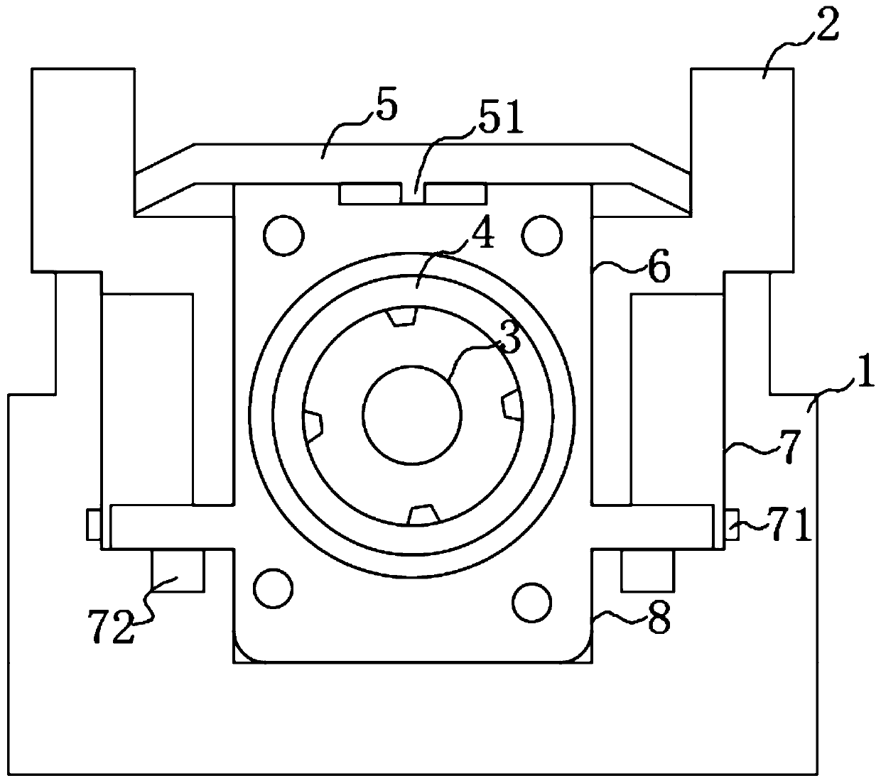
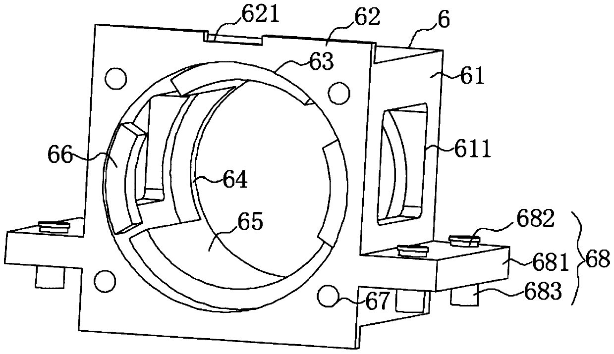
[0018] see Figure 1-2 , the present invention provides a technical solution: an integral fixed seat structure, including a base 1, an upper chute 7 is opened in the middle of the upper end surface of the base 1, and the left and right side walls of the lower part of the inner cavity of the upper chute 7 are both There is a first slide rail 71, and a second slide rail 72 is provided on the left and right sides of the bottom end surface of the upper chute 7, and the inner end of the second slide rail 72 is provided with several threaded holes for connecting bolts 683, The middle part of the bottom end of the upper chute 7 is provided with a chute 8, the bottom of the mounting plate 62 will be engaged in the inner cavity of the chute 8, and the installation wings 68 will be placed on the bottom surface of the inner cavity of the upper chute 7, which is convenient for fixed installation. The fixed seat 6 ensures the stability of the installation of the fixed seat 6. The upper en...

Embodiment 2

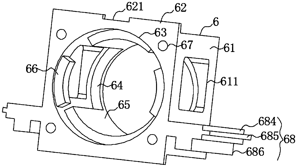
[0021] see figure 1 and image 3 , the present invention provides a technical solution: the installation wing 68 includes a support wing 684, a first slider 685 and a second slider 686, the support wing 684 is fixedly installed on the left and right side walls of the kit 61, the The first sliding block 685 and the second sliding block 686 are respectively disposed on the outer end and the bottom end of the supporting wing 684 . The first sliding block 685 and the second sliding block 686 are movably inserted into the inner cavity of the first sliding rail 71 and the second sliding rail 72 respectively. When installing the fixing seat 6, only the fixing seat 6 needs to be inserted into the upper chute correspondingly from front to back. 7 and the sliding groove 8, because the shape and size of the first slide block 685 and the second slide block 686 are the same as the shape and size of the first slide rail 71 and the second slide rail 72 inner cavity respectively, so that the...


PUM


Abstract

The invention discloses an integral fixing seat structure. The structure includes a pedestal; the middle part on the upper end face of the pedestal is provided with an upper slide groove; the middle part on the bottom end of the upper slide groove is provided with a lower slide groove; a cover plate is fixedly installed on the upper end of the pedestal; a slide seat is movably clamped in the innercavity of the upper slide groove; a leading screw penetrates the middle part at the lower part of the slide seat, and the front side of the leading screw is sleeved by a bearing; the outer sidewall of the bearing is sleeved by a fixing seat; the fixing seat; includes an external member, an installation plate, a clamping ring, first arc-shaped reinforced wings, second arc-shaped reinforced wings and an installation side wing; the first arc-shaped reinforced wings are arranged on the upper and lower sides in the middle part of the inner cavity of a cylindrical through groove; and the second arc-shaped reinforced wings are arranged on the left and right sides on the front side of the inner cavity of the cylindrical through groove. The structure can guarantee the concentricity with a servo motor when the leading screw is operated; the structure can be conveniently installed and dismounted; and the using stability of the fixing seat can be guaranteed, and the stability of the operation ofthe leading screw can be enhanced.

Description

technical field [0001] The invention relates to the technical field of motors, in particular to an integral fixing seat structure. Background technique [0002] When the servo motor is directly connected, in order to ensure the concentricity of the screw rod and the servo motor, it is generally necessary to use a fixed seat for fixing. The existing fixing seat is inconvenient to install and disassemble, the fixing effect is not good, and it is prone to deformation and damage. Therefore, we propose an integral fixing seat structure. Contents of the invention [0003] The purpose of the present invention is to provide an integral fixing seat structure to solve the problems raised in the above-mentioned background technology. [0004] In order to achieve the above object, the present invention provides the following technical solutions: an integral fixed seat structure, including a base, an upper chute is opened in the middle of the upper end surface of the base, and the lef...

Claims


Application Information

Patent Timeline
Patent Type & Authority Patents(China)
IPC IPC(8): H02K7/06
CPCH02K7/06
Inventor 吴仁财
Owner 苏州玖钧智能装备有限公司
Features
  • R&D
  • Intellectual Property
  • Life Sciences
  • Materials
  • Tech Scout
  • Unparalleled Data Quality
  • Higher Quality Content
  • 60% Fewer Hallucinations
Learn More