tank

A fuel tank and steering plate technology, applied in the direction of oil supply tank devices, mechanical equipment, etc., can solve problems such as overheating and pollution

Active Publication Date: 2022-03-08
ROBERT BOSCH GMBH
View PDF9 Cites 0 Cited by
  • Summary
  • Abstract
  • Description
  • Claims
  • Application Information

AI Technical Summary

Problems solved by technology

Furthermore, this can disadvantageously lead to overheating and contamination issues

Method used


Image

  • tank

Examples


Embodiment Construction

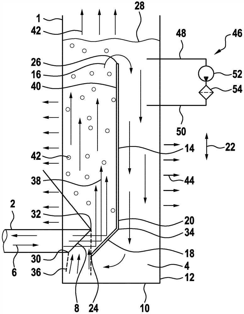
[0028] According to this figure, the tank 1 has a connecting line 2 . Oil can be fed into or removed from the interior 4 of the oil tank via the connecting line. Here, in particular, periodically alternating flow directions 6 are provided in the connecting line 2 . The connecting line 2 has a nozzle opening 8 which extends approximately obliquely with respect to the vertical. The nozzle opening 8 faces here in the direction of the bottom side 10 and the side wall 12 of the tank 1 . A deflection plate 14 is arranged in the tank 1 at a distance from the nozzle opening 8 . The oil flowing into the oil tank via the connection line 2 can be deflected upwards by means of the deflector plate, which overall leads to a circulating flow 16 of oil around the deflector plate 14 .

[0029] The deflection plate 14 has a deflection section 18 and a guide section 20 . The sections 18 , 20 are arranged in an angled manner relative to each other. In particular, the deflection section 18 ex...


PUM


Abstract

An oil tank for a hydraulic system is disclosed, the oil tank having a connecting line via which oil can be supplied to the oil tank and via which oil can be drained from the oil tank. In this case, a diverter plate is arranged in the oil tank in order to guide the oil supplied or discharged via the connecting lines in a defined manner.

Description

technical field [0001] The invention relates to an oil tank for a hydraulic system according to the preamble of claim 1 . Background technique [0002] Oil tanks are known from the prior art which are filled with oil and have connecting lines. Oil can be alternately withdrawn and returned to the oil tank via this connecting line. The connecting line is connected here, for example, to a hydraulic press. The disadvantage here is that heated and / or air-laden or air-buffered oil that is returned can be sucked in again via the connecting line. This in turn can lead to disturbances and irregularities, for example in hydraulic controls, in which an oil tank is installed. Furthermore, this disadvantageously leads to overheating and contamination problems. Contents of the invention [0003] In contrast, the object of the present invention is to propose a fuel tank in which the disadvantages mentioned are avoided or at least occur to a lesser extent. [0004] This object is ach...

Claims


Application Information

Patent Timeline
Patent Type & Authority Patents(China)
IPC IPC(8): F15B1/26
CPCF15B1/26
Inventor G.亨德里克斯
Owner ROBERT BOSCH GMBH
Why Eureka
Try Eureka