
Fold-free bending die applied to plate

A technology for bending molds and plates, which is applied in the direction of forming tools, manufacturing tools, metal processing equipment, etc., and can solve the problems that bending molds cannot complete bending, etc.

Pending Publication Date: 2019-04-19
苏州协朗精密机械有限公司
View PDF0 Cites 0 Cited by
  • Summary
  • Abstract
  • Description
  • Claims
  • Application Information

AI Technical Summary

Problems solved by technology

[0003] However, for some products with high requirements on the external surface, it is necessary to hide such creases as much as possible, which makes it impossible for traditional bending dies to complete this type of bending operation

Method used


Image

  • Fold-free bending die applied to plate
  • Fold-free bending die applied to plate
  • Fold-free bending die applied to plate

Examples


Embodiment 1

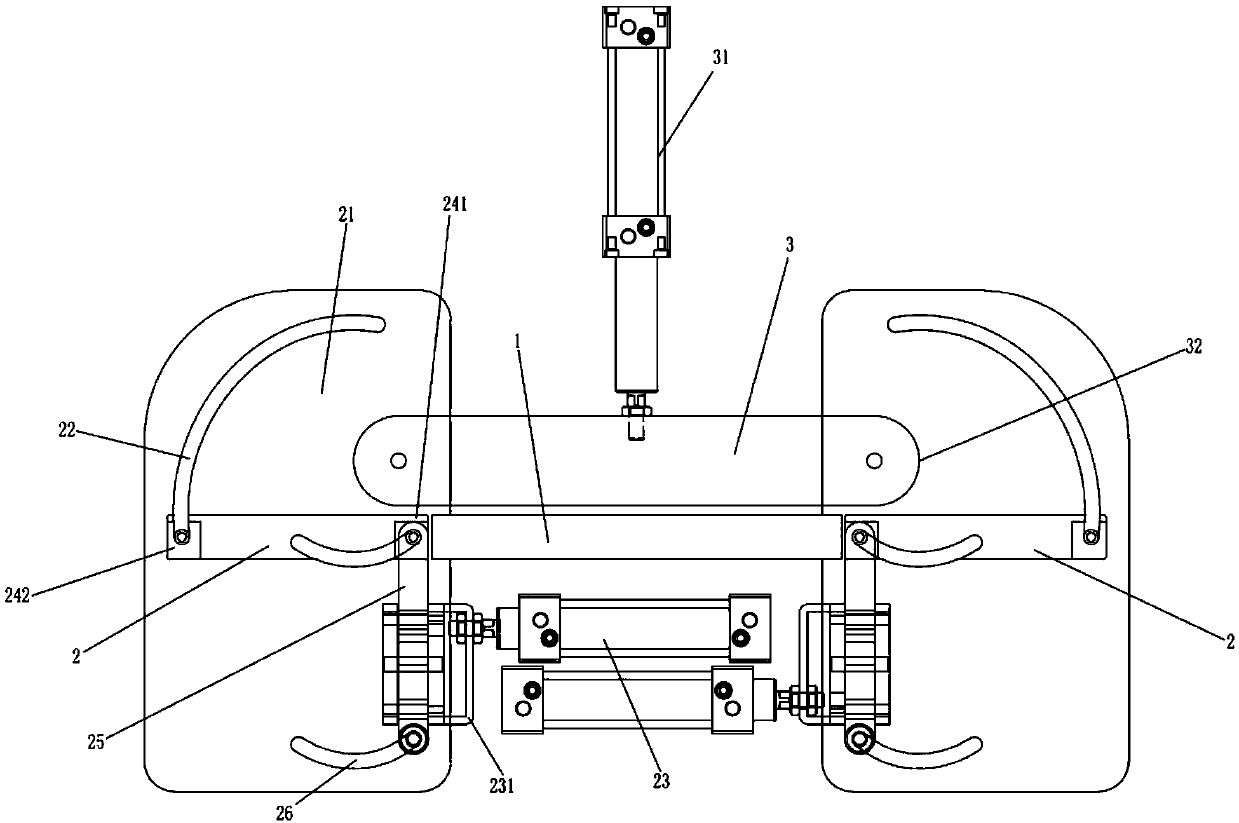
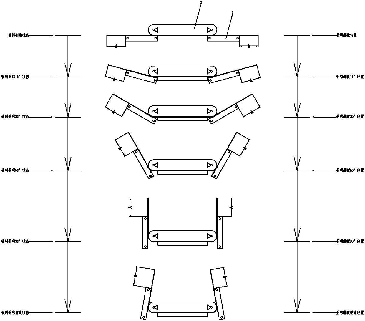
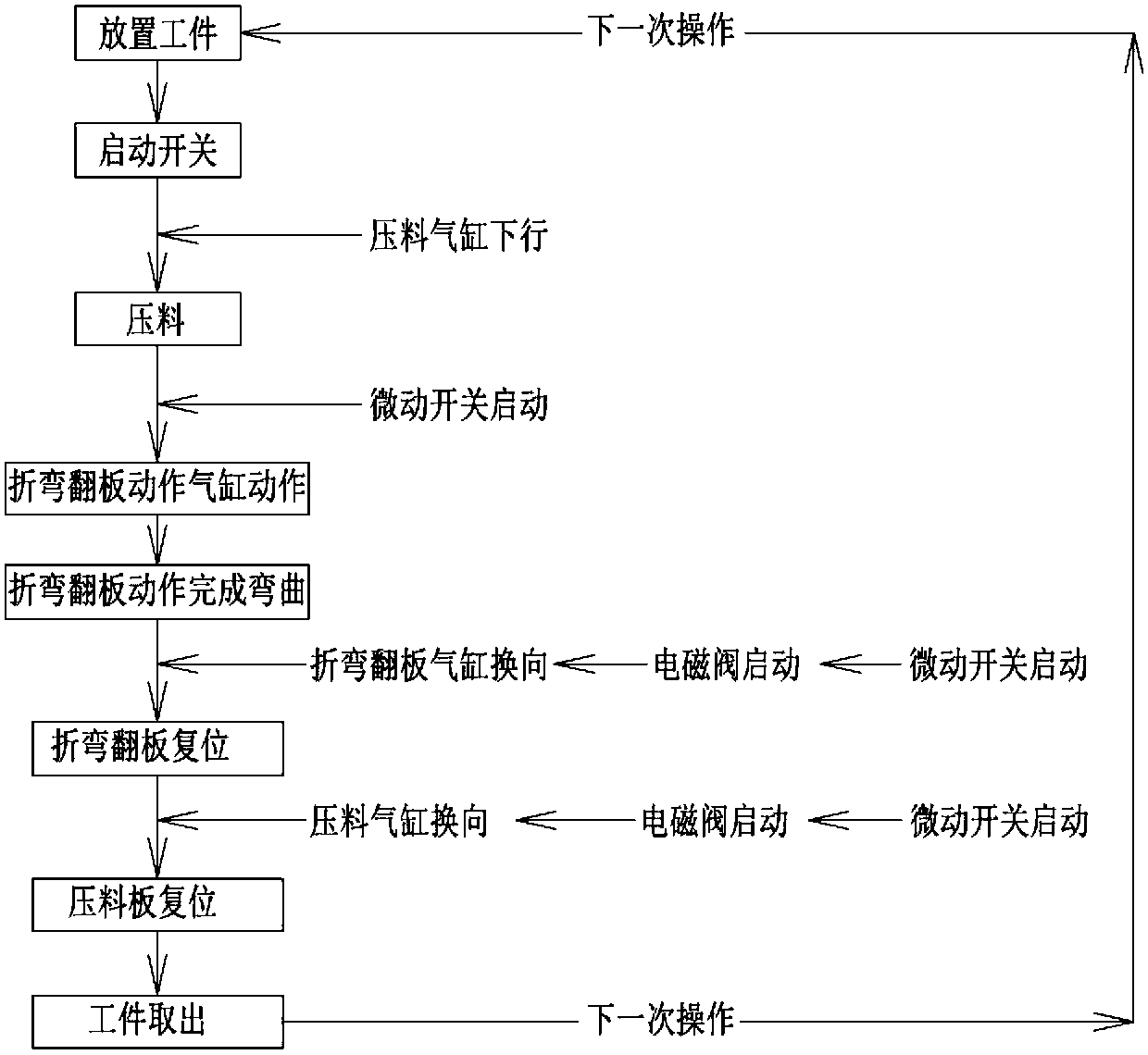
[0023] see Figure 1 to Figure 3 , the figure shows a non-marking bending die applied to plates provided by Embodiment 1 of the present invention, which includes: a clamping plate 1; two bending parts 2, which are symmetrically arranged, and the bending parts 2 are specifically It can be a bent plate, and the two bent parts 2 are respectively arranged outside the opposite ends of the clamping plate 1. The first end 241 of the bent part 2 is hinged on the guide plate 21, and the opposite second end 242 is slidably connected. In the first arc-shaped guide rail 22, the first arc-shaped guide rail 22 is fixedly installed on the guide plate 21, and the bending part 2 is fixedly connected to the first driving part 23 at the same time, and the first driving part 23 drives the bending part 2 to move back and forth; The material plate 3 is installed on the top of the clamping plate 1, the top of the pressure material plate 3 is fixedly connected with a second driving part 31, and the s...

Embodiment 2

[0026] see Figure 1 to Figure 3 , the figure shows a non-marking bending die applied to panels provided by Embodiment 2 of the present invention. On the basis of the above embodiments, this embodiment further makes the following technical solutions as improvements: folding The first end 241 of the curved part 2 is hinged on the end of the guide rod 25, and the guide rod 25 is fixedly connected to the first driving part 23; the guide plate 21 is also fixedly equipped with two parallel second arc guide rails 26, and the guide rod The two opposite ends of 25 are respectively slidably connected in two second arc-shaped guide rails 26 . Through the setting of the above structure, the first end of the bending part can be bent along the arc track to form the end of the product by using the guiding function of the two second arc-shaped guide rails, and the bending force can be effectively controlled. Guaranteed non-marking effect.

Embodiment 3

[0028] see Figure 1 to Figure 3 , the figure shows a non-marking bending die applied to panels provided by Embodiment 3 of the present invention. On the basis of the above embodiments, this embodiment further makes the following technical solutions as improvements: the first A driving component 23 (specifically, an air cylinder) is connected to the bending component 2 through a U-shaped connecting plate 231 . Through the arrangement of the above structure, the U-shaped connecting plate can be used to expand the force application range and force application area of ​​the first driving part.


PUM


Abstract

The invention provides a fold-free bending die applied to a plate. The fold-free bending die comprises a clamping plate, two bending components and a material pressing plate; the two bending components are symmetrically arranged and respectively arranged outside the opposite ends of the clamping plate; the first end parts of the bending components are hinged on a guide plate; the opposite second end parts of the bending components are slidingly connected in a first arc-shaped guide rail; the first arc-shaped guide rail is fixedly mounted on the guide plate, the bending components are fixedly connected with a first driving component at the same time; the first driving component drives the bending components to move back and forth; the material pressing plate is mounted above the clamping plate; the top of the material pressing plate is fixedly connected with a second driving component; the second driving component drives the material pressing plate to move back and forth; two arc-shapedguide surfaces are arranged on the opposite two ends of the material pressing plate; and the arc-shaped guide surfaces form a guide to the side surfaces of the bending components. Compared with the prior art, folds can be effectively eliminated, so that fold-free product bending operation is realized.

Description

technical field [0001] The invention relates to a bending die, in particular to a traceless bending die applied to a plate. Background technique [0002] At present, for the bending processing of some plates such as iron plates and copper-nickel plates, the bending process is usually carried out on a bending die, and certain creases will inevitably be left after bending. [0003] However, for some products with high requirements on the external surface, it is necessary to hide such creases as much as possible, which makes it impossible for traditional bending dies to complete this type of bending operation. Contents of the invention [0004] In view of this, the present invention provides a no-mark bending die applied to a plate that can realize no-mark bending. [0005] For this reason, the present invention provides a kind of non-marking bending mold applied to plate, and it comprises: [0006] clamping plate; [0007] Two bending parts are symmetrically arranged, and...

Claims


Application Information

Patent Timeline
IPC IPC(8): B21D5/02B21D37/10
CPCB21D5/0209B21D5/0281B21D37/10Y02P40/57
Inventor 陈伟
Owner 苏州协朗精密机械有限公司
Learn More